

Propeller Circuit Template And Best Practices
 Mahonroy
Posts: 175
Mahonroy
Posts: 175
in Propeller 1
Hey guys,
I am wanting to come up with a circuit template that can be used for any new propeller projects in the future. It seems that the propeller schematics out there are incorrect and out dated. It also seemed there was a lot of misc. info floating around on the best practices to use, and I want to incorporate it all into my diagram.
This diagram is basically something that every circuit schematic/design should start out with if its containing a propeller microchip. (That is my goal)
The main things that will most likely be different on a case by case basis are how the power rails are set up. Some people might need more/less amperage, some people might want to use a switching buck/booster regulator versus a linear regulator. I included how you might set up 2x examples below.
Here is what I have so far and I would appreciate any input. If something should be changed please let me know along with the reason and I will update the diagrams:
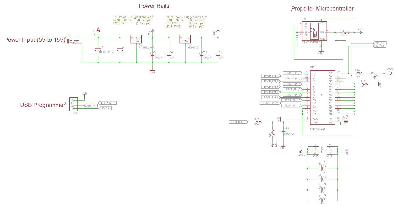
If you need +5v and +3.3v power rails:
If you need only +3.3 power rail:
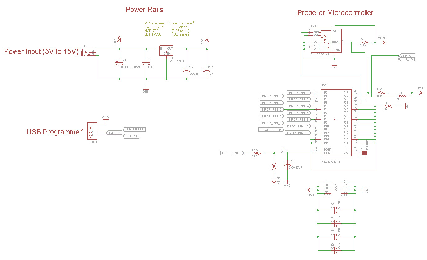
* SDA on EEPROM Pull-Up: From what I have seen on the propeller documentation, and in the datasheet for the "24LC256-I/SN", this should be a 2K or a 2.2K resistor (pull-up to 3.3 volts).
* USB RX & TX Pull-Up: Both of these lines should be pulled up so they are not floating when USB is disconnected. This will help with EMF/EMI problems as well. 10K standard pull-up resistor.
* Reset: The USB reset comming from the programmer should go through a 220 ohm resistor before connecting to the reset pin on the propeller. Even though I have heard that the propeller reset pin has an internal pull-up resistor, from my own personal experience this does not seem to be the case. I have experienced random reset problems in the past due to EMF/EMI problems and a pull-up resistor solved it. For this reason a more stronger 1k pull-up resistor paired with a small capacitor (0.0047 uF) capacitor should be standard on every design.
* Unused Propeller I/O pins: I have heard that unused propeller pins should be set as inputs (they are set to inputs by default at program start anyways) and they should not be floating... instead they should be pulled either high or low. I have them all connected together and then pulled low. I have heard that each pin should have its own separate pull-down resistor, but this seemed a bit ridiculous as it would add so many extra components to the board. The reason for pulling down unused I/O pins is for EMF/EMI protection.
Questions:
* Bulk power capacitors: The propeller documentation states to use 1000uF bulk capacitors on every power rail. I have had a few designs where space would not allow for such a large capacitor so I used a 220uF instead... and everything worked out fine. 1000uF capacitors are also more expensive if they are unnecessary. How do we determine what kind of bulk capacitor we need to be using with our design? Also, what bulk capacitor should be used with a bare bones propeller circuit?
* Does anything need to be done to the circuit in the event of the USB Programmer being plugged/unplugged while powered on or off? Or will my current diagram suffice?
Thanks and any help is greatly appreciated!
I am wanting to come up with a circuit template that can be used for any new propeller projects in the future. It seems that the propeller schematics out there are incorrect and out dated. It also seemed there was a lot of misc. info floating around on the best practices to use, and I want to incorporate it all into my diagram.
This diagram is basically something that every circuit schematic/design should start out with if its containing a propeller microchip. (That is my goal)
The main things that will most likely be different on a case by case basis are how the power rails are set up. Some people might need more/less amperage, some people might want to use a switching buck/booster regulator versus a linear regulator. I included how you might set up 2x examples below.
Here is what I have so far and I would appreciate any input. If something should be changed please let me know along with the reason and I will update the diagrams:
If you need +5v and +3.3v power rails:
If you need only +3.3 power rail:
* SDA on EEPROM Pull-Up: From what I have seen on the propeller documentation, and in the datasheet for the "24LC256-I/SN", this should be a 2K or a 2.2K resistor (pull-up to 3.3 volts).
* USB RX & TX Pull-Up: Both of these lines should be pulled up so they are not floating when USB is disconnected. This will help with EMF/EMI problems as well. 10K standard pull-up resistor.
* Reset: The USB reset comming from the programmer should go through a 220 ohm resistor before connecting to the reset pin on the propeller. Even though I have heard that the propeller reset pin has an internal pull-up resistor, from my own personal experience this does not seem to be the case. I have experienced random reset problems in the past due to EMF/EMI problems and a pull-up resistor solved it. For this reason a more stronger 1k pull-up resistor paired with a small capacitor (0.0047 uF) capacitor should be standard on every design.
* Unused Propeller I/O pins: I have heard that unused propeller pins should be set as inputs (they are set to inputs by default at program start anyways) and they should not be floating... instead they should be pulled either high or low. I have them all connected together and then pulled low. I have heard that each pin should have its own separate pull-down resistor, but this seemed a bit ridiculous as it would add so many extra components to the board. The reason for pulling down unused I/O pins is for EMF/EMI protection.
Questions:
* Bulk power capacitors: The propeller documentation states to use 1000uF bulk capacitors on every power rail. I have had a few designs where space would not allow for such a large capacitor so I used a 220uF instead... and everything worked out fine. 1000uF capacitors are also more expensive if they are unnecessary. How do we determine what kind of bulk capacitor we need to be using with our design? Also, what bulk capacitor should be used with a bare bones propeller circuit?
* Does anything need to be done to the circuit in the event of the USB Programmer being plugged/unplugged while powered on or off? Or will my current diagram suffice?
Thanks and any help is greatly appreciated!
1665 x 867 - 206K
1376 x 839 - 172K
Comments
DO NOT connect IO pins together as you have. If you need them pulled to ground, then put a resistor per pin (I often use SIP packages with eight resistors and a common pin).
The 1000uF caps on your power supply seem excessive, but I'll leave that to the analog guys to comment on.
I've attached a PDF of my own Propeller starter circuit.
I am guilty of leaving the pullup resistor off the SCL line but in general design practice you should include one. The pullup value can be 10k if the devices are on-board and close or use 2k2 if you have I2C run off the board as in the case of displays etc.
Use RX/TX pullups of 10k and also many times since I rarely place USB circuitry on the board itself I also add series current limit resistors, 1k to the Rx and Tx. There are not many designs where it is useful to have USB built-in, especially when you consider how the Prop gets used. I prefer to have a standard 4+4 pinout that matches the Prop Plug plus has I2C and +5V connections as I have my own USB converters that use all 8 pins. The connector also proves useful for attaching I2C displays etc or for field programming updates as I have a small Prop board that when it is plugged into this connector it becomes powered from the target, holds the Prop in reset and loads the EEPROM directly. Very simple quick and clean.
Any sensitivity to EMI is usually poor pcb layout etc as in all the scores and scores of designs I've done in industrial apps I've never had "reset" problems ..... ever. But if you run the reset line off the board during normal operation then expect problems, or just avoid it.
The crystal circuit is often neglected but it is the most sensitive since it is running in linear mode and the whole chip relies on the oscillator. Keep the crystal leads as short as possible and use your ground plane or guard rails. For this reason avoid the old HC49 crystals, especially the gull-wing SMD versions as they exacerbate EMI problems. There are plenty of cheap and tiny cylindrical TH crystals or many small SMD types but in this respect consider using 10MHz as they are perfectly fine for designs that run at 3.3V etc.
Unused pins should either be pulled up/down or simply set as outputs. There is no problem having a common pullup/down but then again I use tiny SMD resnets that pack 4 resistors into the space of one and are just as easy to handle.
edit: there is not a problem with tying unused inputs together, the trouble is that they are I/O and subject to whatever software tells them to do. As mentioned, I prefer to set them to outputs and avoid all this redundant pullup stuff.
Ok so the SCL should be pulled to 3.3v with a 10k pullup, I will add that to the schematic. I will also add the diode to the power input as this is good practice.
Peter, could you elaborate on your explanation of the USB circuitry being on the board or off the board? I was not completely following your explanation. Are you saying you flash the EEPROMS seperately, then solder the propeller and EEPROM to the board without the usb connector? And in this case you would never be able to reflash the EEPROM without something like pogo pins?
I do remember those small 10Mhz crystals... is there anything else special that would have to be changed in order to use them? Just an alteration to the clk frequency variable in SPIN and thats it? I agree the large gullwing crystal is a drag.
So it looks like I need to figure out what to do with the bulk capacitors as it seems the 1000uF that is mentioned in the propeller documentation is excessive. Any ideas for this?
Thanks again!
The 1000uF is fine as the filter capacitor on line frequency supplies, but to provide adequate filtering for digital circuitry lower capacitance and lower ESR capacitors like a 10uF tantalum are a better fit.
Thats the thing though, is I am wondering if the 1000uF capacitor is necessary. 1000uF capacitors are large and expensive, and if they are not needed then it seems like a waste.
-Phil
Don't ever accept the fact that just because XYZ uses 1,000uf caps "after" a regulator that this is ever good design practice. I've seen it done perhaps because 5V motors are attached to the same 5V logic supply and the regulator can't handle the start-up currents from the motors. A Q&D fix is simply to use a whopping big capacitor but this should never make its way into a production design for a whole variety of reasons. I have used 1,000uf electros on the bulk unregulated DC input on old designs that were run from transformers and I have used them in designs that need to power motors although these motors always operate off the bulk supply, never the logic voltages.
btw, 1,000uf caps are not expensive, not when you buy them in bulk that is.
Anyone can Fritz a circuit and it may work but a good PCB layout is everything for a reliable design, hence my choice of crystals etc although your layout looks good from what I could see in another thread (!).
if driving a high power motor load (again, storing charge), but completely unnecessary
for a logic board. The regulator handles timescales of 10^-5 seconds or more, your bulk
decoupling only has to last 10us or so. If the board uses 0.1A, a 10uF cap will hold out
for 10us with only 100mV drop which is perfectly adequate for logic.
With a switching regulator you might find it only responds on more like a 100us timescale,
in which case 100uF is suggested, but a lot of modern switchers use really high frequency
switching and 10uF is usually good enough. If in doubt still a 'scope on the rail to see
how much its flickering with the load.
In any event, DO NOT tie them directly to Vcc or Ground.
We all make simple errors in our programs -- you'll be very sorry if you do this.