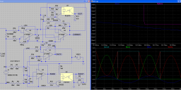
Mains voltage, current, and zero-cross measurement circuit - feedback!
 Peter Jakacki
Posts: 10,193
As part of a project I am working on I need to detect the zero-cross and voltage of each of 3 phases, typically 240VAC here or 110VAC. I've come up with a suitable circuit that operates over isolated supplies and would be interfaced to a 12-bit A/D of a small micro that is responsible for transmitting the zero-cross and voltage serially across the isolation barrier.
There's also a current sense amplifier that I intend to use directly on the 2,200A+ bus bar itself but this requires its own isolated circuitry. It's not strictly necessary but I want to monitor as many parameters as possible in case of a big bang.
I've simulated it as best as I can and the schematic is fudged somewhat to enable LTSpice to simulate and display the results. Only one half of the cycle is used to measure the current and the buffered voltage to the A/D is inverted on the negative half of the cycle so that I don't need negative supplies or biasing arrangements plus I can use the full resolution of the A/D. That's also why the AC voltage has been reduced down so low too just so the opamp works properly on the negative swing with the single supply voltage. My previous design just used the receiver from an RS485 transceiver to deal with larger negative swings but reducing the voltage low enough seems to do the trick for opamps.
The zero-cross comparator also helps to add a bit of hysteresis to the signal too via the voltage sense opamp's feedback.
I will probably need a better opamp for the current measurement too since I will be sensing less than 5mV for a current of over 2,200A although there are already big current transformers for the intelligent circuit breaker.
So from those in the know, what do you think? Is it workable enough for the first prototype? Suggestions please.


Comments
The neutral is useful for voltage measurements but the main loads will probably be delta config so I need to sense it on the active. I'm bolting the PCB right onto the bus bar with two bolts which also happen to be the current probes.
Hi Peter,
you probably have seen those
analog.com/en/products/analog-to-digital-converters/integrated-special-purpose-converters/poly-phase-metering-ic/ade7932.html#product-overview
or the other iCoupler based (isolated) AD converters. Mostly Delta-Sigma.
Hi Markus, I guess this circuit grew out of a need for a reliable and precise zero-cross because an important consideration of the measuring circuit is not for metering per se but regulation so I want to gather and process information from one half-cycle and apply it "by" the next. I don't think these metering chips would be too flexible for that purpose. However in saying that the front-end chip might be useful for the current measurements as this figure is mostly used for fault handling and logged for diagnostics.
Anyway, my line of attack is to eliminate the calibration issues around the optocouplers by using the AD7401 to convert to serial bitstreams. Other options are to use SPI based ADCs. This keeps the analogue front-end very simple. For each of the current and voltage; an isolated 1 Watt, 5 Volt regulator and just a small R-C network in front of the AD7401.
It should still be applicable for you, Peter, since I'm still reading the raw waveform, albeit filtered, and doing the metering later in software.
I used LTSpice initially so that I could experiment with zero-cross circuits.
You can use a lead-lag design that uses a series R and shunt C (which removes RF and noise spikes ) and then a series R-C gives slight phase lead to compensate for the phase lag of the LPF.
Final noise removal can be in SW via a DPLL.
Or you can get totally carried away and have a microcontroller measure and maintain an average time between zero crossings and use that as the basis for calculating the exact time of the zero point.