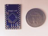
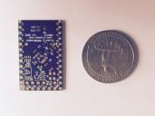
P8XBlade2: Cluso's new series of Propeller Development Boards
 Cluso99
Posts: 18,071
Here is the first board in a new series of P8XBlades...
Cluso's P8XBlade2
A tiny P8X32A Propeller Development Board 0.78"x1.28" (19.8x32.5mm) (1.98x3.25mm)


* PCB 0.78"x1.28" (19.8x32.5mm)
* P8X32A QFP44 Propeller Chip
* 12MHz SMT Crystal (overclocked to 96MHz)
* EEPROM 64KB (24C512)
... preprogrammed with SD boot loader
... with WE (write enable) pcb link (default disabled)
* Onboard 3V3 voltage regulator circuit
... board requires regulated 5VDC-6VDC such as USB power
...3V3 output (low current) is brought out to a pcb pad
* microSD socket
... for my Propeller Operating System "PropOS"
* RST features a 10K pullup plus an optional transistor reset circuit selectable by pcb link (default both disabled)
* P31 & P30 feature series protection resistors (0/68R/136R selectable by solder bridge) and 3V6 zener diode to ground (default 136R)
* P29 & P28 feature 10K pullup resistors on both SDA & SCL (EEPROM)
* P12..P15 connect to the microSD DO/CLK/DI/CS pins respectively
* All P0..P31 & RST propeller pins are brought out to pads on a 0.1" grid, as are +5V input, 3V3 output, and GND. Pins are supplied, but not fitted/soldered.
* All SMT parts are reflow soldered

PropOS is compilation of open source Objects contributed by the Propeller community. Commands are similar to MSDOS.
An expensive PropPlug is not required. Programs can be transferred via the microSD card (optional extra).
A cheap USB-TTL/Serial converter can be connected to P31/P30. +5V & GND may also be supplied via this converter.
The total board size is less than 1.00sqin so I can feature it on Hackaday's <1sqin projects. Nope - the contest is for < 1"x1"
PCBs have arrived. Just waiting for a few SMT components to arrive
Cluso's P8XBlade2
A tiny P8X32A Propeller Development Board 0.78"x1.28" (19.8x32.5mm) (1.98x3.25mm)


* PCB 0.78"x1.28" (19.8x32.5mm)
* P8X32A QFP44 Propeller Chip
* 12MHz SMT Crystal (overclocked to 96MHz)
* EEPROM 64KB (24C512)
... preprogrammed with SD boot loader
... with WE (write enable) pcb link (default disabled)
* Onboard 3V3 voltage regulator circuit
... board requires regulated 5VDC-6VDC such as USB power
...3V3 output (low current) is brought out to a pcb pad
* microSD socket
... for my Propeller Operating System "PropOS"
* RST features a 10K pullup plus an optional transistor reset circuit selectable by pcb link (default both disabled)
* P31 & P30 feature series protection resistors (0/68R/136R selectable by solder bridge) and 3V6 zener diode to ground (default 136R)
* P29 & P28 feature 10K pullup resistors on both SDA & SCL (EEPROM)
* P12..P15 connect to the microSD DO/CLK/DI/CS pins respectively
* All P0..P31 & RST propeller pins are brought out to pads on a 0.1" grid, as are +5V input, 3V3 output, and GND. Pins are supplied, but not fitted/soldered.
* All SMT parts are reflow soldered

PropOS is compilation of open source Objects contributed by the Propeller community. Commands are similar to MSDOS.
An expensive PropPlug is not required. Programs can be transferred via the microSD card (optional extra).
A cheap USB-TTL/Serial converter can be connected to P31/P30. +5V & GND may also be supplied via this converter.
The total board size is less than 1.00sqin so I can feature it on Hackaday's <1sqin projects. Nope - the contest is for < 1"x1"
PCBs have arrived. Just waiting for a few SMT components to arrive


Comments
Now that is a small board, especially when you write:
I think perhaps you mean cm and not mm!
A couple comments:
12MHz may be a bit much as the PLL will multiply that up to 192MHz before dividing it down to 96MHz.
Why not change the order of the the P30,P31,RST,GND pins so a normal "prop plug" can be connected ?
I would put a GND on one of the long sides, so it can be fitted as a DIP device. (Maybe make it 14 pins long?).
Bean
I think it is not 0.6" wide. so that becomes a problem ?
The low xtal freq of a prop gives problems these days, as most small SMD crystals start with higher MHz
HC49/US is still the lowest price point, but is large.
I see a
NX8045GB-6MHZ-STD-CSF-3
but that is (8.00mm x 4.50mm)
Oscillator modules continue to come down in price, and they are available small, so maybe a PCB option for one of those ?
eg mouser show stocks of Epson
SG-210STF 6.2500ML3
which is a compact (2.50mm x 2.00mm) and 1.8mA
an irony of modern part volumes, is that a part like
TG-5035CJ-12N 26.0000M0
which has GPS sub ppm precision, is lower cost than many Oscillator modules.
(Similar are AVX KT2520K2 KT2016K2 )
Of course, 26MHz is of not much use with a Prop 1 PLL
(hopefully, it will work with Prop 2 PLL )
A Prop 1 compromise that covers most normal uses, could be a Ceramic Resonator -
Murata CSTCR come in 5MHz and 6MHz (4.50mm x 2.00mm)
Thanks. (BTW I am not being defensive - here is my reasoning)
Note that I have called this board the P8XBlade2. I specifically trimmed the edge down from 0.8x1.3" to achieve the magic <1sqin measurement
The 1 version is 0.8x0.8" and the 3 version is 0.8x1.6" - currently I don't intend to make them available.
The 1 version removes the uSD and shifts P9..P14 horizontally between P8 & P15.
The 3 version adds a microUSB connector and moves P25..P27 to the right long row and GND, P29, P28 to the left long row.
I have prototype pcbs of both versions.
As for the PropPlug compatible pinout, IMHO it's no longer a viable proposition because it's too expensive. The connection is loosely based on the current cheapest USB-TTL/Serial board - CP2102 based is less than $2 including shipping. Its pinout is 3v3/GND/+5V/TXD/RXD/DTR. The GND/+5V/TXD/RXD matches my pinout and DTR must be shifted right 0.1". 3V3 MUST NOT be connected! It wasn't possible for me to move the DTR pin 0.1" left (no pad space!).
However, with an OS (PropOS or whatever), the prop can run a program (incomplete) to download code without requiring reset (run an alternate program), or the program can be written directly to the uSD card in the PC (via USB or SD adapter). It can also do FTF (done) and can re-program the EEPROM (done).
re 12MHz xtal... IIRC Chip confirmed that the PLL tops out at about 14.3MHz which is what I also confirmed. The DIP package can run to 15MHz (weird isn't it). You might also note that there are two vias at 0.1" at the xtal pins. These can take a watch can 5MHz or 6MHz or HC19U/S with pins bent inwards. Unfortunately the tiny smt xtals do not come in 5/6/6.5MHz and I need this size to fit.
12MHz has been chosen because I intend to complete the Prop USB LS/FS code to run to USB directly. Note the 68 ohm serial resistors on P31 & P30. There is also an uncommitted 1K5 pullup resistor on the board that is required for LS/FS USB
As for bread-boarding into a solderless breadboard, it will plug into a solderless breadboard leaving 2 exposed links either side, or use two breadboards - one either side of the board. the breadboards are cheap enough.
I have additional boards coming... One is this board as a proto-board, and one is this board with linkable circuits similar to my TriBlade - details withheld
BTW to make this all fit, I had to go down to a mix of 0603 and 0402 parts.
Going to be fun hand-loading 0402's that I can hardly see. At least I have a reflow oven.
USB sounds a great idea.
There are Oscillator modules at 6MHz, so an alternate footprint for one of those should fit ?
I'm sure there will be revisions
Running at 6MHz places the VCO in the middle of the range, and a 6MHz Oscillator is smaller with more controlled PPM than a 6MHz crystal.
You could also use a > 3.3V, good tolerance regulator to buy some margin when overclocking.
Digikey show 331 choices from 3.35-3.5v
I almost always clock my boards at 6.5MHz (104MHz). Occasionally I have also used 13.5MHz (108MHz).
Sapieha ran one of my boards for 6 months continuously with a 15MHz xtal (120MHz) - it used a DIP40.
But in this case I want to use the board at 96MHz for simplicity of USB emulation, hence the reduction in speed.
I am not going to crank the voltage up as I am happy with Chip's comments previously about the PLL top seed.
Yeah I'm gonna be that guy:
Looks like a typo in your cm conversion. How about (1.98x3.25cm) ?
Boards look good. As usual.
The RamBlade is a different board because it uses 30 of the 32 available pins. This board replaces my 1"x1" CpuBlade while adding uSD and a few other parts, and is intended for those that want a cheap miniscule development board with all pins brought out, and includes a uSD interface so you can run a simple OS.
I have 2 new RamBlade's partially done (the old one is still available). It moves the I/O back to pins 30/31 - so it's marginally slower. The uSD card is also on different pins and requires an additional decoding IC which will not fit in the P8XBlade 1/2/3 designs which all use the same base prop circuit in a 0.8"x1.0" section.
I have 2 current ideas about the new RamBlade - the resultant circuit is the same. One is a pair of stacked 0.8"x1.0" boards - advantage tiny!!. The other is a single pcb currently about 0.8"x1.7" or equivalent in area by increasing width and reducing length - larger but single pcb. I will only build one.
Bad typo - the size of the crystal
This board is also in the centre of larger Prototyping board, basically 0.1" pad grid.
It's also in the centre of a larger board with linkable...
* uSD
* VGA
* TV (Composite video)
* Audio (stereo)
* PS2 Keyboard & Mouse (via 1xPS2 or 2xUSB-A)
* 2x Sigma-Delta inputs
* uUSB-B with configurable soft/jumpers - lots of potential uses on a uUSB-B connector
* 2x uncommitted 3mm LEDs
* small section of prototype board (0.1" pad grid)