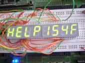
Using MAX7219 with Common Anode Displays
 tomcrawford
Posts: 1,129
in BASIC Stamp
Conventional wisdom says you cannot use the ubiquitous MAX7219 with common anode displays. It says so right in the data sheet: "Drive Common-Cathode LED Display". From time to time we hear from someone who bought common anode sticks that they ended up not using. I wondered if it is possible.
Here is a diagram showing a "typical" 4-digit display,both common cathode (top schematic) and common anode (bottom schematic):
One can see that they BOTH have anodes that are tied together and cathodes that are tied together. In fact, when you think about it, you see that they both are matrixes and that two sticks constitute an 8 x 8 diode matrix. You just have to connect them so that the cathodes are tied to the Digit pins and the anodes are tied to the Segment pins of the MAX7219. The way I wired it up, the LED segment A's are connected to DIG0 (MAX register 1) and the segment DP's are connected to DIG7 (MAX register 8). The right-most digit of the LED is connected to MAX SEG G and the left-most digit is connected to MAX SEG DP. Head-bone connected to the Knee-bone.
But programming the registers is very messy because when you write a register, instead of writing one digit, you are writing a given segment of all the digit. The attached code shows how I did this. I am reminded of the person who likened something like this to "Moving a dead whale from Santa Cruz to Monterey by kicking it down the beach".


