Propeller resetting when actuating relay
in Propeller 1
I have found discussions of similar problems but the solutions don't completely fix it in my case.
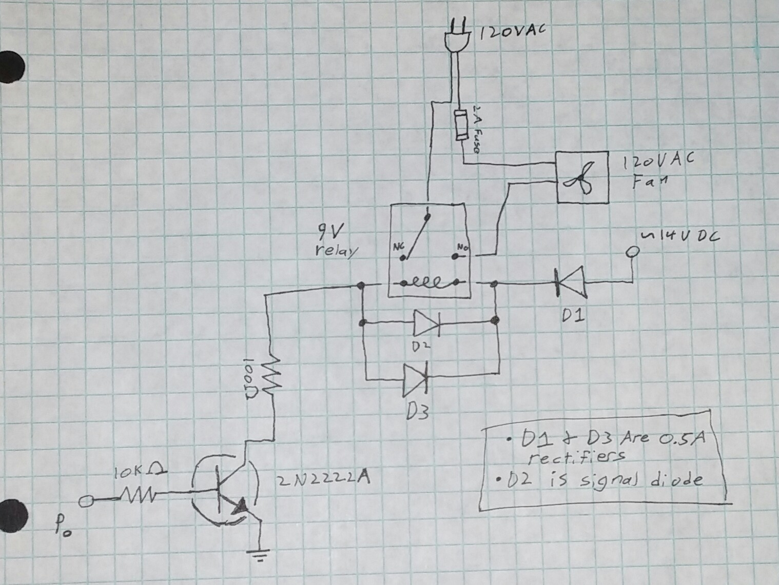
I'm using the propeller to actuate a relay that switches a 120VAC fan. My schematic:

Currently, when the relay is switched, about 20% of the time the propeller resets. Before I added D1, D3 and additional capacitors to all my power circuitry (including the 14V, 9V, 5V and 3.3V which is not pictured) it reset ~90% of the time. Of all those changes adding D1 made the largest difference. The 100 Ohm resistor was selected because it was the largest resistance with which the relay would always trigger. My BOEn is grounded. My relay is glued face down and so I cannot provide a part number but I know it is rated to switch 120VAC.
I believe the issue is when the 120VAC is switched there's often enough emf produced and picked up by the relay coil to send a pulse into my power circuitry that triggers a reset of the propeller chip. I believe this because if I unplug the 120VAC triggering the relay never causes a reset. Interestingly however I cannot find/see a significant power deviation with my oscilloscope. There are very small fluctuations though, up to 100mV. Providing oscilloscope images would be impractical.
So my question is how should I further isolate the relay from my power circuitry so that the propeller never resets? Or otherwise fix the issue if someone sees/thinks of something I'm not thinking of.
Thanks so much in advanced. I love electronics and have been messing with parallax micro-controllers and therefore lurking on these forums for a while but this is the first time I've ever needed to ask a question. This problem is unusually frustrating for me as I've never been stumped by something that seems so simple.
Oh and when I say I added more capacitors I mean it. I've got 1000uF caps everywhere now haha. Also, I have a capacitor literally right on top/across of the propeller.
I'm using the propeller to actuate a relay that switches a 120VAC fan. My schematic:
Currently, when the relay is switched, about 20% of the time the propeller resets. Before I added D1, D3 and additional capacitors to all my power circuitry (including the 14V, 9V, 5V and 3.3V which is not pictured) it reset ~90% of the time. Of all those changes adding D1 made the largest difference. The 100 Ohm resistor was selected because it was the largest resistance with which the relay would always trigger. My BOEn is grounded. My relay is glued face down and so I cannot provide a part number but I know it is rated to switch 120VAC.
I believe the issue is when the 120VAC is switched there's often enough emf produced and picked up by the relay coil to send a pulse into my power circuitry that triggers a reset of the propeller chip. I believe this because if I unplug the 120VAC triggering the relay never causes a reset. Interestingly however I cannot find/see a significant power deviation with my oscilloscope. There are very small fluctuations though, up to 100mV. Providing oscilloscope images would be impractical.
So my question is how should I further isolate the relay from my power circuitry so that the propeller never resets? Or otherwise fix the issue if someone sees/thinks of something I'm not thinking of.
Thanks so much in advanced. I love electronics and have been messing with parallax micro-controllers and therefore lurking on these forums for a while but this is the first time I've ever needed to ask a question. This problem is unusually frustrating for me as I've never been stumped by something that seems so simple.
Oh and when I say I added more capacitors I mean it. I've got 1000uF caps everywhere now haha. Also, I have a capacitor literally right on top/across of the propeller.


Comments
-Phil
Doing that definitely improved things but it still occasionally resets....
And yes I do have 3.3V regulator (LM2937-3.3) for the Propeller... just checked it's output (for the first time in a week or 2) and it's outputting 3.73V now
So maybe that's part of the problem and obviously I need a new 3.3V source before continuing...
You would need a very good oscilloscope to catch this.
The problem is relay closure/open and bounce can occur at any part of the mains cycle and that can generate >> 100V with a rise time under 1ns.
With typical PCB track inductances, it needs very little capacitance (fractions of 1pF) to couple enough of that energy into more sensitive electronics.
Using a Solid state relay is best, but failing that increase the distances where you can - think of the mains-side as aggressive RF, and ferrite beads may help.
I guess solid state relays don't switch as discretely?
Can you reword what you mean by "but failing that increase the distances where you can"?
eg the post quoted below suggests 'chaining relays', which gains separation distance and places two small capacitances in series :
Haha yea I just realized I have some wires for a temperature sensor (different sub-circuit) lying right beside the mains cable
Thanks for all the input! I definitely have some stuff to try I didn't before. I don't want to try anything else until I get a new 3.3 Volt regulator (don't think it's safe to run Prop off 3.7V, is it?). Just ordered them. I also ordered some solid state relays. I'll comment what happens/what I figure out when I get that stuff. Though I'll probably go solid state I do want to be able to do this right with coil relays; just on principal. Being able to switch 120VAC with a micro-controller controlled relay is absolutely something I should be able to do. Electronics always surprises me how complex things that seem simple can be.
Snubbers go across contacts, not coils (maybe he meant contacts). The coils have clamp diodes and D1 (and the other diodes) can be a fast diode like a Schottky as normal diodes will not react fast enough to spikes. 1,000uF electros are very poor spike suppressors, bigger is not better, just use little 0.1uF ceramics etc in the right places as these have very low inductance and impedance at high frequencies (spikes).
Yes, that coupling from the mains is always a thing to watch out for.
I do have some ceramics placed around. I'll have to acquire some Schottky diodes.
-Phil
Contact snubbers should be R-C in series, as C alone is a little brutal on the contacts.
They need a little care as they represent a relay-off current path, and the R needs to be surge rated ( power resistor ) & the C mains rated with lightning spike margins.
You are talking about "snubbers" on A/C solenoids and the OP is talking about a relay driving a fan. It's ok to mention but it can also be confusing to the OP. We are talking about snubbers across the relay contacts where it will normally arc.
I use snubbers at work all the time across coils and contacts. Here's one I've used with success. Of course you could make your own.......see data sheet for values.
I understand the distinction; on some inductive AC loads you need a snubber in parallel with the AC device but here we are talking about a snubber across the switch itself. Correct?
Will it kill my prop to use it with 3.7V?
If it used to be 3.3V then something is awry. If it is oscillating, that means higher peaks.
Meter Vcc with a fast, small signal diode and check it is < 3.7v.
What happens to Vcc if you add a (say) 50mA load ?
It's not oscillating.
Nothing. It is quite steadily 3.7V no matter the load.
Unplugging the AC fan circuit dropped my ~3.7V about 4mV.
Curious... a strange failure mode.
Are you using the same meter that gave 3.3V before ?
-Phil
Yes. It's an RSR MS8217. I have changed the batteries though? I measure 3.6V with my oscilloscope.
The largest tantalum I have is .47uF....
Why doesn't parallax make this recommendation in their literature I wonder?
Maybe my 2nd meter is right though. It says 3.3V almost exactly and I have changed the batteries on my 1st meter since the last time I checked with it... Still though I'd find it odd my scope and 1st meter give similar readings