HELP AGAIN
in BASIC Stamp
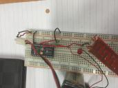
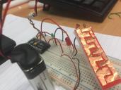
Hi guys. I need help. As seen in images attached, my output 14 is connected to a green LED. Output(s) 9 and 11 are connected to a buzzer and a red LED respectively. The grounds of the red LED and buzzer is connected through the sensor that I have made. In which the sensor shows a open circuit, no current will pass through. The objective of the sensor acts as a water sensor as previous post mentioned. When water comes in touch between the two copper strips, current will then be able to pass through. Now, I need to program the basic stamp, such that, when there is no water detected, the green light will be active. And IF there is water detected, outputs 9 and 11 will be active and thus output 14 will be deactivated. Any idea how? I don't know how to write the program despite reading the manual. Only able to get the basics. Any experts here that can give me a helping hand? Tried using the if else but to no avail.


Comments
The Grounds for the Red LED and the Buzzer should both be connected directly to the ground rail since the BS2SX controls them.
You also don't have current limiting resistors on the LEDs and if you look at Page 18 of the BASIC Stamp Manual, it states that each pin can source 30 mA, which a lot for most LEDs. What's a Microcontroller uses 470 Ohm resistors.
Also 30 mA is not enough current to drive the buzzer so you will need to use a transistor.
Page 291 of What's a Microcontroller gives an example of using a Transistor to turn on an LED.
Do you know what voltage and current your buzzer uses?
Page 70 of What's a Microcontroller shows how to control an LED with a switch.
Notice the 10K Pull-Down Resistor on the Pushbutton.
The circuit has a resistor connected to Vss. This resistor is called a pull-down resistor because it pulls the voltage at P3 down to Vss (0 volts) when the button is not pressed.
The program on Page 72 blinks the LED 10X per second if the button is pressed, otherwise it stays off.
The HIGH command will turn the LED on while the LOW command will turn it off.
That should get you started.
You sensor works the same as a pushbutton so when it's activated (INsensor = 1) you turn the Green LED off (LOW 14), the Red LED on (HIGH 11), and the buzzer on (HIGH 9). Otherwise (ELSE) you turn the Green LED on (HIGH 14), the Red off (LOW 11), and the buzzer off (LOW 9).
DO
DEBUG ? IN7
IF (IN3 = 0) THEN
HIGH 14
PAUSE 0
ELSE
HIGH 11
PAUSE 0
FREQOUT 9, 4000, 1500
PAUSE 500
FREQOUT 9, 500, 1500
PAUSE 500
FREQOUT 9, 500, 1500
PAUSE 500
FREQOUT 9, 500, 1500
PAUSE 500
FREQOUT 9, 500, 1500
PAUSE 500
FREQOUT 9, 4000, 1500
PAUSE 500
FREQOUT 9, 500, 1500
PAUSE 500
FREQOUT 9, 500, 1500
PAUSE 500
FREQOUT 9, 500, 1500
PAUSE 500
FREQOUT 9, 500, 1500
PAUSE 500
LOW 14
PAUSE 0
ENDIF
LOOP
You have your sensor connected to Pin 7 but you are checking the value of Pin 3 so it's no wonder that your program only runs once.
Based on all the FREQOUT statements your buzzer must be a piezoelectric speaker.
Also is you look on page 199 of the BASIC Stamp Manual you will see that the BS2 uses units of 1 ms and 1 Hz while your BS2SX uses units of 0.4 ms and 2.5 Hz.
On page 201 there is a FREQOUT demo program which uses Conditional Compilation to automatically adjust the values for you but it also demonstrates the PIN directive.
An I/O pin can be treated just like a variable which makes programs easier to write, read, and modify.
You could add PIN declarations for your sensor, green LED, and red LED and then change the pin numbers in the program to their declared names.
Your buzzer sequence is very long so the first thing you should do is turn off the Green LED.
Also you never turn off the Red LED should the sensor turn off again.
How often do you plan to check your sensor because your buzzer sequence is very long, 17000 ms or 17 seconds?
' {$STAMP BS2sx}
' {$PBASIC 2.5}
DO 'execute programme
DEBUG ? OUT14 'verify input port
IF (OUT14 = 0) THEN 'condition for programme to execute
HIGH 1
PAUSE 0
ELSE
HIGH 13 'on red LED
PAUSE 0
FREQOUT 12, 500, 1500 'Buzzer sounds from output 9, 1500Hz and 4 seconds
PAUSE 500 'Pause for 0.5 seconds
FREQOUT 12, 500, 1500
PAUSE 500
FREQOUT 12, 500, 1500
PAUSE 500
FREQOUT 12, 500, 1500
PAUSE 500
FREQOUT 12, 500, 1500
PAUSE 500
FREQOUT 12, 500, 1500
PAUSE 500
FREQOUT 12, 500, 1500
PAUSE 500
FREQOUT 12, 500, 1500
PAUSE 500
FREQOUT 12, 500, 1500
PAUSE 500
FREQOUT 12, 500, 1500
PAUSE 500
LOW 1
PAUSE 0
ENDIF 'End programme
LOOP
You changed the Pin numbers and PAUSE 0 is so short that it doesn't do anything.
I am guessing your switch moved to P11.
I simplified the code and added some comments so it should be easier to understand.
The Check loop runs every 1/4 second (250 ms) while the Alarm loop will run every 500 ms (1/2 second).
' -----[ Title ]----------------------------------------------------------- ' Elderly Wetness Alarm System ' {$STAMP BS2sx} ' {$PBASIC 2.5} ' Wiring Schematic ' P11 - 220 ohm (RED-RED-BRN) --- Switch (Normally Open) - Vdd ' |_ 10K (BRN-BLK-ORN) - Vss ' 220 ohm resistor protects the Stamp I/O pin ' 10K resistor pulls I/O down to ground when switch is inactive ' P12 - (+)Piezospeaker - Vss ' P13 - 470 ohm (YEL-VIO-BRN) - A_Red LED_C - Vss ' P14 - 470 ohm (YEL-VIO-BRN) - A_Green LED_C -Vss ' 470 ohm reistors limit the current the LED gets to about 7 mA ' i_LED = V_LED / R_LED = (5V - 1.7 V) / 470 = 3.3 V / 470 ohm = 0.00702 A = 7 mA ' -----[ EEPROM Data ]----------------------------------------------------- ' This program has no EEPROM Data ' -----[ I/O Definitions ]------------------------------------------------- SwitchPin PIN 11 ' Wetness Switch connected to P11. SpeakerPin PIN 12 ' Piezospeaker connected to P12. RedLED PIN 13 ' Red LED connected to P13. GreenLED PIN 14 ' Green LED connected to P14. ' -----[ Constants ]------------------------------------------------------- AlarmDuration CON 200 ' BS2sx Duration of Alarm tones (ms) ' BS2sx Duration = BS2 Duration * 0.4 = (500 ms) * 0.4 = 200 ms AlarmFrequency CON 3750 ' BS2sx Frequency of Alarm tones (Hz - BS2sx) ' BS2sx Frequency = BS2 Frequency * 2.5 = (1500 Hz) * 2.5 = 3750 Hz AlarmDelay CON 500 ' Delay between Alarm tones (ms) ' -----[ Variables ]------------------------------------------------------- alarmCounter VAR BIT ' Beeps when 1 and pauses when 0. ' -----[ Initialization ]-------------------------------------------------- PAUSE 1000 ' Wait for Serial Port to stabilize alarmCounter = 0 ' Initialize counter. ' -----[ Program Code ]---------------------------------------------------- ' This program only has a Main Routine ' -----[ Main Routine ]---------------------------------------------------- DO ' Main Loop (runs forever) DEBUG ? SwitchPin ' Print Switch value to the Debug Window IF (SwitchPin = 0) THEN ' Check if Switch is active LOW RedLED ' Turn off Red LED (Reset) HIGH GreenLED ' Turn on Green LED alarmCounter = 0 ' Reset Alarm Counter PAUSE 250 ' Wait for 1/4 second ELSE ' Activate Alarm if Switch becomes active LOW GreenLED ' Turn off Green LED (Reset) HIGH RedLed ' Turn on red LED DEBUG "Alarm...", CR ' Code taken form ActionTones.bs2 in WAM. IF (alarmCounter = 0) THEN ' Check if Counter is 0 FREQOUT SpeakerPin, AlarmDuration, AlarmFrequency ' Sound Alarm tone ELSE ' Pause if Counter is 1 PAUSE AlarmDelay ' Pause between Alarm tones ENDIF ' End of Alarm IF...THEN...ELSE statement alarmCounter = ~alarmCounter ' Invert Counter (Flips value between 0 and 1) ENDIF ' End of Main IF...THEN...ELSE statement LOOP ' End of Main DO...LOOP ' -----[ Subroutines ]----------------------------------------------------- ' This program has no SubroutinesYou have the switch wired wrong.
VDD(21) ---- Switch – 10.5K (BRN-BLK-GRN-RED-BRN) - GND
|_ 240 Ohm (RED-YEL-BRN-GOL) – P11(16)
If you look you will see that VDD (5V) connects directly to P11 through the 240 Ohm Resistor, so the program will always see a 1 and that's why the alarm routine always runs.
The connection point show be AFTER the switch, not before it. Also notice how the I/O is in the middle of a "see saw" with VDD on one side and VSS (Ground or GND) on the other.
VDD(21) - Switch –-- 10.5K (BRN-BLK-GRN-RED-BRN) - GND
|_ 240 Ohm (RED-YEL-BRN-GOL) – P11(16)
In this placement the I/O pin sees Ground (VSS) through the 10K resistor but when the switch connects the pin will be "pulled up" to 5V (VDD).
You need to move the 10K resistor over one row so that it connects directly to the 240 Ohm. Swap the Red and Black switch wires so the black wire is connected to both the 240 Ohm and the 10K. Move the Red switch wire and the Red wire from VDD (Pin 21) to an unused row.
You should see a 0 on the screen and the green LED should be on until you touch the switch.
Sorry for not replying sooner.
Block diagrams are used for complex circuitry but your project uses only basic circuits.
A simple hook-up diagram should be enough to explain how everything is hooked up.
The Flow Chart is based on the older "Industrial Control" text (Experiment #1).
http://laspace.lsu.edu/aces/Document/Parallax Docs/Industrial Control.pdf