Isolated RS-485
 Duane Degn
Posts: 10,588
in Propeller 1
I think my boss wants to have an isolated RS-485 connection on a project with which I'm helping.
I initially thought an isolated RS-485 just meant optically isolated but I didn't see how something could be isolated if both sides of the optical isolation shared the same power supply.
Sure enough the power supply to the optical isolation also needs to be isolated (I'm not sure if this is a "need" or a "should" be isolated).
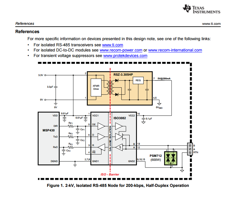
I find the following reference diagram in a TI app note.

Here's a 5v to 5v isolated supply I found on Mouser.
http://www.mouser.com/ProductDetail/RECOM-Power/RBE-0505S/?qs=sGAEpiMZZMvGsmoEFRKS8EFGozA47QQ4lf7QgFWqt78%3d
Am I correct to think it doesn't do much good to optically isolate a connection without also isolating the power supply?
We'll be use a Propeller which of course is a 3.3V device but we'll have both 3.3V and 5V on the board. Is there any advantage to using one input voltage than another? Should I be looking for a 3.3V to 5V isolated power supply or is a 5V to 5V supply fine?
I initially thought an isolated RS-485 just meant optically isolated but I didn't see how something could be isolated if both sides of the optical isolation shared the same power supply.
Sure enough the power supply to the optical isolation also needs to be isolated (I'm not sure if this is a "need" or a "should" be isolated).
I find the following reference diagram in a TI app note.
Here's a 5v to 5v isolated supply I found on Mouser.
http://www.mouser.com/ProductDetail/RECOM-Power/RBE-0505S/?qs=sGAEpiMZZMvGsmoEFRKS8EFGozA47QQ4lf7QgFWqt78%3d
Am I correct to think it doesn't do much good to optically isolate a connection without also isolating the power supply?
We'll be use a Propeller which of course is a 3.3V device but we'll have both 3.3V and 5V on the board. Is there any advantage to using one input voltage than another? Should I be looking for a 3.3V to 5V isolated power supply or is a 5V to 5V supply fine?


Comments
Depends on what the requirement is. I have worked on equipment where parts of the circuitry are communicating over optically isolated connections and the "grounds" at each end are separated by 15000 volts?
I put "grounds" in quotes because basically there was digital logic at each end operating from what it thought was a ground and 5v rail. Just happened to be 15KV offset from what they were talking too.
In a situation like that I might suggest it is pointless isolating the communication signals if you are not also taking care of the power supply arrangements.
Ouch! 15KV?
The examples I've looked at are good up to 2KV. I'll need to ask my boss what level of protection is needed.
I'm guessing the higher the voltage difference the more the parts are going to cost.
Thanks for the insight Heater.
I typically use Maxim's family of RS485 communications parts, I believe they do include a set which is indeed isolated.
Cheers,
Peter (pjv)
Depends on what 'attacks' the isolation is to protect against.
Some designs do optically isolate, even though the grounds are essentially the same and that protects against ESD and faults propagating.
Adding local small, but isolated, power improves the degree of isolation as the pathways from the hostile outside world, to more sensitive electronics are reduced. - DC paths are broken, and AC pathways become the residual pF coupling.
When looking at isolated PSUs, check the pF coupling as well.
I build isolation amplifiers and I use the Ti Iso124 this amp also has a compatible dc to dc converter in a dip package p/n dcp011515. So I would follow the ap note and use the recommended power supply. The iso124 data sheet shows a good 3 way isolation.
I'll try to figure out the pros and cons of these various parts so I can let my boss know what options are available.
I'll probably be back with a schematic for you guys to look over.
Thanks again for your help. I've learned a lot from this forum.
I didn't clutter the schematic with filter or bypass caps. You'll know what to do about those.
-Phil
It's not clear from your first post, but is this a multi-drop network app, or just point-to-point? If the latter, I would seriously consider going to RS422 instead of RS485. Full duplex is much simpler, both from a hardware and a software standpoint. In my circuit above, for example, you could switch to an RS422 transceiver and eliminate one of the optos. The only additional requirement is an added twisted pair.
-Phil
@Phil, I a had originally thought something like you suggested would be used but then I found out there were chips which include opto isolation with the balanced signal producing circuit.
I think the sensor will most often be used in a point to point configuration but I'm pretty sure it needs to support multi-drop. We're using a Modbus protocol to send and receive data and I think single duplex is all that is planned. The sensor will be a slave device and only reply when data is requested.
I believe we'll use a 24VDC supply with both 5V regulator and 3.3V regulator (discussed in an earlier thread) on the sensor board (with a Propeller). I don't think we'll have a second (external) power supply to power the circuit on the outside portion of the opto isolation. Which is why I'm wondering if we need an isolated DC to DC supply.
Would a beefy diode and a second 5V regulator from the 24V supply be a viable option? I haven't researched all the options mentioned earlier so maybe one of these parts would do the trick. I kind of like the "jelly-bean parts" concept since I think I can understand what each part is doing. (I hadn't heard the phrase "jelly-bean parts" but I think I understand what it means from context and analogy.
BTW, I helped with an earlier version of this sensor but my boss is planning an upgrade and wants to include isolated outputs. I'll probably be asking about isolated 4-20mA circuits once I know enough to hopefully ask an intelligent question on the topic.
-Phil
Once you get to the 4-20mA stuff, take a look here for another "jelly-bean" approach:
http://forums.parallax.com/discussion/comment/631965/#Comment_631965
-Phil
Thanks Peter.
I think the meter I'm working on is intended for industrial stuff but I don't think it will be connected to things in other buildings. I doubt we need lightning protection but I'll check to make sure.
@Phil, Thanks for link. I haven't seen a current driver done like that before. Not that I know a lot about this sort of stuff.
I've also used the LTC2862, which is a 3.3V or 5V part, but not isolated. I mention it because it has high ESD ratings (15kV HBM), as well as extended common mode range and fault tolerance. Other manufacturers make such things too. If you are mainly concerned with ESD events and not with chronic ground loops and widely different industrial ground potentials, it might be okay to skip the extra hassle, power consumption, and expense of full isolation. Or should it be, better safe than sorry whatever the expense?
That's an interesting idea. I've always used the Burr-Brown now TI XTR101/RCV420 parts. But that's just me.
As for the RS485 stuff, I use the parts from Maxim for the stuff. (Sometimes also from TI.)