Programming the Altera MAX 10M50 device with a P1V image
 ozpropdev
Posts: 2,793
Hi All
I managed to get P1V running on Altera's Max10 Dev kit over the weekend.
This board is fitted with the 10M50 device and fits 8 cogs nicely with 160K of hub ram.
Her's the relevant results of the 8 cog 160k hub test build.
A lot of time was wasted trying to program the board via Quartus programmer.
Success was finally achieved by ignoring the Altera documentation completely.
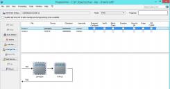
Here are the steps to program the device from Quartus Programmer Version 15.0.2
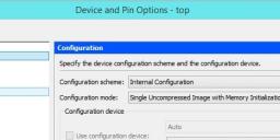
Before compiling the verilog code make sure to set the configuration as follows.
In the "Devices" dialog press the "Device and Pin Options" button.

Compile your code. Quartus will generate a .sof and a .pof file.
Now start the programmer.
1. Press "Auto detect"
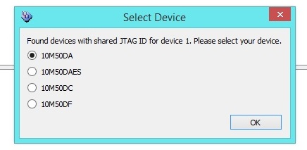
Quartus will give you 4 choices, select te first option (10M50DA) Ok
2. Highlight the first device and press "Change file"
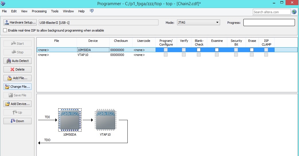
3. You have two choices at this point.
A. Select the .sof file for ram based fpga image.
B. Select the .pof file for Flash programming of your image.
4. Check the program/configure checkbox.
5. Press "Start" to program the device.
6. Have fun!
I managed to get P1V running on Altera's Max10 Dev kit over the weekend.
This board is fitted with the 10M50 device and fits 8 cogs nicely with 160K of hub ram.
Her's the relevant results of the 8 cog 160k hub test build.
Device	10M50DAF484C6GES
Total logic elements	17,491 / 49,760 ( 35 % )
Total combinational functions	15,784 / 49,760 ( 32 % )
Dedicated logic registers	5,542 / 49,760 ( 11 % )
Total memory bits	1,441,792 / 1,677,312 ( 86 % )
A lot of time was wasted trying to program the board via Quartus programmer.
Success was finally achieved by ignoring the Altera documentation completely.
Here are the steps to program the device from Quartus Programmer Version 15.0.2
Before compiling the verilog code make sure to set the configuration as follows.
In the "Devices" dialog press the "Device and Pin Options" button.

Compile your code. Quartus will generate a .sof and a .pof file.
Now start the programmer.
1. Press "Auto detect"
Quartus will give you 4 choices, select te first option (10M50DA) Ok

2. Highlight the first device and press "Change file"

3. You have two choices at this point.
A. Select the .sof file for ram based fpga image.
B. Select the .pof file for Flash programming of your image.
4. Check the program/configure checkbox.
5. Press "Start" to program the device.
6. Have fun!


Comments
BTW What speed are you clocking at?
P1V became erratic at 150 MHz so stepped back to 143.75 MHz (50MHz x 23 / 4)
So far seems Ok, but further stability testing needed though.
Shame the 10M50DA chips are all well over $100 ea from Mouser/DigiKey and nil stock
I suspect that the bit shift, rotate instructions are the area causing the erratic behaviour.
I base this "guess" around the fact that my tests seem to have trouble in the multiply/divide opeartions in spin.
When time permits a test suite needs to be created to isolate the troublesome instruction.
Perhaps a tweak here and there to the Verilog might allow the clock speeds to increase again.
Still happy with 125 MHz though.