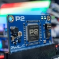
Through-hole plug-in M/F jumpers for Electronic Conference Badge
 Ken Gracey
Posts: 7,419
Hey all,
As we prepare to release the new Electronic Conference Badge at Parallax we're finding that we need a way for people to easily jump the I/Os from a soldering through-hole area to a breadboard. Although these badges are not available yet, we're already running activities with them in conjunction with Northwestern University in Chicago.
I need some help finding these jumpers - a little Google work showed I didn't even know the keywords.
The ideal parts would be wires that plug into the 0.1" through-hole area on the badge, making contact. They'd probably have some springing "push-in" design so they can make contacts with the plated-through holes on the badge. The other side of the wire could plug into a breadboard for more circuits. Ideal length is 4-6". One thing to avoid with these wires is when the M side is wider than 0.1" - yes, I've seen this before. Some of the M/M jumper wires have these fat little finger-grabbing locations that are so wide you can't place several wires next to each other.
Anybody know where to find these? I need to stock them, so an idea source is a low-cost, high-volume one.
Thanks,
Ken Gracey


Comments
-Phil
Autosplice:
http://www.autosplice.com/compliant-pin-selection-guide.html
The 74095 series of SL headers from Molex have compliant pins. These are shrouded headers, but do have a standard 0.025" square pin.
http://www.molex.com/molex/products/listview.jsp?query=74095
Mill-Max:
https://www.mill-max.com/products/results/76
Single press fit pins are widely used in the automotive industry to reduce costs because in many cases, soldering processes are eliminated entirely:
http://www.interplex.com/products/solderless-pressfit-for-automotive
-Phil
https://www.sparkfun.com/tutorials/114
-Phil
http://www.schmartboard.com/index.asp?page=products_jumpers
http://www.digikey.com/product-detail/en/D01-9970642/952-1986-ND/3727951
or
http://www.digikey.com/product-detail/en/4320-01074-0/811-2702-ND/2344918
Then they've created their own breadboard!
Just plug in/out whatever components/jumper wires they need.
(Note.. those example parts may not be the most optimal- they come in different heights/styles/etc... That can be refined later if the idea has merit)
So this is a wire assembly, Male-male ?
How many ways ? 2? 3? 4 ?
The stagger the holes slightly suggestion above is the cheapest retention system, that works a little better on more pins.
There are also varying 'barrel' forming options for press-fit (one image above) but they will push up the price and are not really designed for multiple-reuse.
Cheapest looking forming is this
http://p.globalsources.com/IMAGES/PDT/B1023252710/Pin-Header.jpg
which just 'whacks' a standard pin to deform half the material in each direction.
One problem we have found with formed leads, is the "degree of whack" adds another variable, and batch-batch variations occur.
Gets points for robust and flexible, and the PCB incremental cost is very low.
If the boards are done and the intended connections are to be made to plated holes, 0.040" inside diameter, finished dimensions, 0.1" spaced, then E-Mark Inc makes these eight color coded sintered glass bead, through hole spring type design test points that are suitable for holding test clips or even soldered to jumper wires.
They also have options for 0.052" plated finished inside diameter holes, but the glass bead will not fit in 0.1" spaced holes.
If Parallax wants to assemble its own jumpers, perhaps they could satisfy your needs.
Henrique
At page 04 of their catalog:
e-markinc.com/images/EmarkCatalog.pdf