Preventing USB Resets with an I/O Pin
 Duane Degn
Posts: 10,588
A little over a year ago, I asked if there were a way to prevent a USB connection from resetting the Propeller.
Several people suggesting using an I/O pin to prevent the reset circuit from activating. Here's tonyp12's reply:
I'm trying to translate Tony's words into a schematic but I don't think I'm doing it right.
I've come up with three different options, I'm hoping you guys will let me know if one of these options is better than the others or even better, let me know if there's an alternative I missed (I'd be surprised if there aren't).
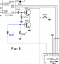
My first thought was to use an I/O pin to pull the gate base on the reset transistor low harder than the FTDI chip will pull it high.
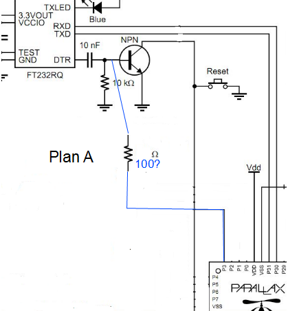
(I cropped the Demo Board's schematic a bit too small and cut off the reset pin. Hopefully it's obvious where the reset line is and where it's headed in these schematics.)
I'm not sure if this is a good idea. The more I think about the less I like it.
My next option was to attempt to "AND" the low logic levels by adding a second transistor.
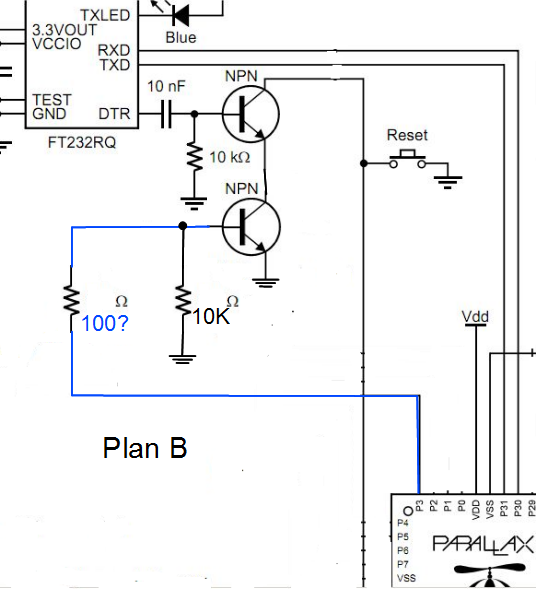
My gut is telling me the above circuit is also probably a bad idea. Is there a better way to arrange the transistors?
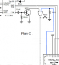
After thinking a bit more, I realized my attempt to "AND" the low pulse is the same as using an "OR" gate on a high pulse. Here's my "Plan C" attempt:
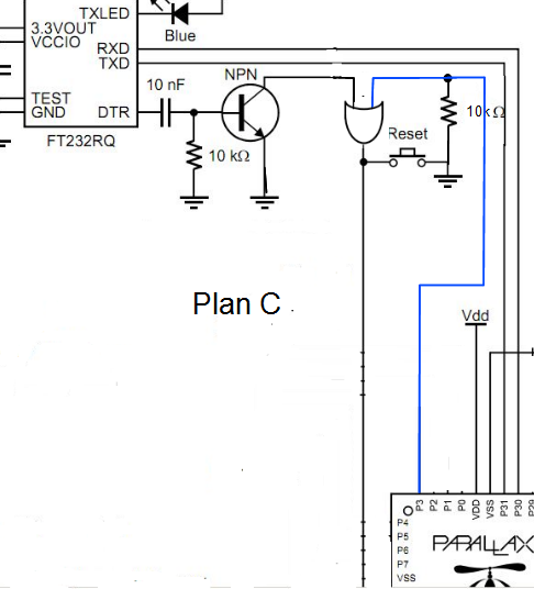
My gut doesn't mind this one. It seems like a reasonable fix. Looking through Digikey I found this OR gate.
http://www.digikey.com/product-detail/en/74AHC1G32SE-7/74AHC1G32SE-7DICT-ND/2639311
Of course the less expensive the circuit the better and the few parts the better.
Which of the plans I list here have a good chance of working?
Is there a better solution?
Edit: I fixed my error in calling the transistor's base the gate.
Several people suggesting using an I/O pin to prevent the reset circuit from activating. Here's tonyp12's reply:
Yes having a Prop pin as output with a high or low state to override any DTR signal using some resistors
and when it's time to reprogram a power reset gives you 4 seconds to click send in prop-tool
as your program have not yet set the pin from the default input after a hardware re-boot.
My choice would be to force a state on the Transistor Base.
I'm trying to translate Tony's words into a schematic but I don't think I'm doing it right.
I've come up with three different options, I'm hoping you guys will let me know if one of these options is better than the others or even better, let me know if there's an alternative I missed (I'd be surprised if there aren't).
My first thought was to use an I/O pin to pull the gate base on the reset transistor low harder than the FTDI chip will pull it high.
(I cropped the Demo Board's schematic a bit too small and cut off the reset pin. Hopefully it's obvious where the reset line is and where it's headed in these schematics.)
I'm not sure if this is a good idea. The more I think about the less I like it.
My next option was to attempt to "AND" the low logic levels by adding a second transistor.
My gut is telling me the above circuit is also probably a bad idea. Is there a better way to arrange the transistors?
After thinking a bit more, I realized my attempt to "AND" the low pulse is the same as using an "OR" gate on a high pulse. Here's my "Plan C" attempt:
My gut doesn't mind this one. It seems like a reasonable fix. Looking through Digikey I found this OR gate.
http://www.digikey.com/product-detail/en/74AHC1G32SE-7/74AHC1G32SE-7DICT-ND/2639311
Of course the less expensive the circuit the better and the few parts the better.
Which of the plans I list here have a good chance of working?
Is there a better solution?
Edit: I fixed my error in calling the transistor's base the gate.


Comments
-Phil
Here's plan D.
I admit to not understanding why using a Schottky diode is better than just a straight connection.
Wouldn't the Prop prevent a reset with or without the diode in series? Does the diode protect the Propeller's I/O pin?
Thanks again for your help.
-Phil
The 10nF capacitor directly in series between DTR and the transistor base gives too much base drive. It can cause a nasty-looking reset pulse as it overloads the FTDI chip. (Yes, I know it is standard practice, but that doesn't make it right!) I'd recommend 10k resistor in series with 1nF in place of the 10nF, and that in turn will make inhibiting the pulse easier with schottky diode or resistor.
Yes, I don't know why that cap value is so large but on a similar note I have used 1nf directly from the DTR to the Prop reset without the transistor circuit. Even though it was a kludge it seems to work fine and I haven't had any problems with about 50 of these units that were made.
@Duane: In this case if you wanted to inhibit the DTR reset you could have the 10k from DTR to the cap to reset and have the inhibit line connected directly to the junction of the RC but drive it high to disable reset. KISS!
Tracy, thanks for the information. I'll pass on the suggestion.
BTW, I just tried the Schottky diode trick and it worked great. I used an old Propeller Proto Board USB to test. It was kind of eerie to hear the USB chime as I reconnected because this has always signalled a board reset in my mind. I then see my little test program still happily counting away with large numbers indicating the board had not reset.
In case anyone's interested, here my little test program.
CON

  _clkmode = xtal1 + pll16x
  _xinfreq = 5_000_000            ' 80MHz overclock

  RESET_INHIBIT = 3

OBJ

  Pst : "Parallax Serial Terminal"

PUB Main : count

  Pst.Start(115200)

  Pst.Clear

  repeat
    Pst.Home
    Pst.Str(string(11, 13, "count = "))
    Pst.Dec(count++)
    if count > 100
      dira[RESET_INHIBIT] := 1
      Pst.Str(string(11, 13, "reset inhibitted "))
    Pst.ClearEnd
    Pst.Newline
    Pst.ClearBelow
    waitcnt(clkfreq / 10 + cnt)
If I unplug the USB before the count reaches 100, then the board resets when reconnected. After 100 is reached the I/O and Schottky diode do their job the board doesn't reset.
I'm not surprised this fix worked but I'm still unreasonably excited to have an USB connection not reset the board. In fact I'm so excited, I'm going to force you all to see my test board.
Yeah, I suppose you're right, it's not a very exciting picture. It is exciting to be able to inhibit a reset even though it costs an I/O pin.
Thanks again Phil for your help.
It's one thing to say "this should work" and another to say "I tested this and it does work". I didn't want the first test of the circuit to occur after a new batch of PCBs were made.
The PPB USB has close by when I was looking for a way to test the circuit so it's the board I used.
The PBC will be in some sort of industrial enclosure so the software solution is a much better option than using a switch or jumper.