

Interface BS2 with an independently powered DC Circuit
 AndyMenon
Posts: 26
AndyMenon
Posts: 26
Hi folks,
First of all, I'm creating this new thread after having consulted another forum post on "using BS2 to connect to a rain gauge powered by a 12V independent circuit". Whatever I have done thus far is based on that thread.
What needs to happen:
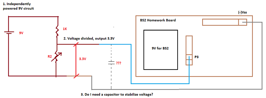
Please see the attached diagram. I want the BS2 chip to read the 3.3V signal at P3 and based on that, I want it to perform a series of actions. I will expand on this idea as this discussion progresses as I want to solve the problem one step at a time.
What has been completed already:
I have my output voltage divided down to 3.3V. I can read it with my multi-meter. The circuit is shown in the attachment.
Symptoms of the Problem:
When the wire is connected to the (-)Vss, the program reads 0 at IN3.
But when I pull out the connection to (-) Vss, I see my program reads 1,1,0,0,1,1,1,0 .... in short, a stream of inconsistent 1s and 0s.
Question 1: Is the circuit that connects to the BS2 Homework board as shown in the sketch correct?
Question 2: Why am I getting inconsistent reads at IN3 when I pull out the connection to (-)Vss? Do I need a capacitor to stabilize the voltage at IN3?
Once I manage to resolve this issue, and reliably read the input at IN3, I should be able to code the rest of the actions.
Thanks for your help!
Andy
First of all, I'm creating this new thread after having consulted another forum post on "using BS2 to connect to a rain gauge powered by a 12V independent circuit". Whatever I have done thus far is based on that thread.
What needs to happen:
Please see the attached diagram. I want the BS2 chip to read the 3.3V signal at P3 and based on that, I want it to perform a series of actions. I will expand on this idea as this discussion progresses as I want to solve the problem one step at a time.
What has been completed already:
I have my output voltage divided down to 3.3V. I can read it with my multi-meter. The circuit is shown in the attachment.
Symptoms of the Problem:
When the wire is connected to the (-)Vss, the program reads 0 at IN3.
But when I pull out the connection to (-) Vss, I see my program reads 1,1,0,0,1,1,1,0 .... in short, a stream of inconsistent 1s and 0s.
Question 1: Is the circuit that connects to the BS2 Homework board as shown in the sketch correct?
Question 2: Why am I getting inconsistent reads at IN3 when I pull out the connection to (-)Vss? Do I need a capacitor to stabilize the voltage at IN3?
Once I manage to resolve this issue, and reliably read the input at IN3, I should be able to code the rest of the actions.
Thanks for your help!
Andy
888 x 327 - 27K
Comments
Let me try to piece together all of this in parts:
A. To your point on 3.3V, I guess I'm ok here as long as the voltage is between 1.4V and 5.0V which the BS2 can take safely.
B. I guess I will have to revisit my fundamentals on BS2 which BTW is dated by a couple of years or so and will research the pull-up / pull-down resistors.
C. About the capacitor - I will have considerable noise as this system will be mounted on a car that has a beefy and noisy 230hp truck engine.
I do want both wires from the incoming 3.3V to be in constant connection with the stamp.But if I did connect it to Vdd, how would I read that input in code and take decisive action to trigger another circuit?
When the 3.3V cuts off, I will need the stamp to trigger a relay to shut down a circuit on the car.
Thanks
Andy
If I understand your question #2, when you pull the lead to Vss your BASIC Stamp no longer has a ground reference for the voltage level on P3. Between two independent circuits you must have a common ground in order to know the voltage on the signal wire.
What happens when I replace this prototype with the actual application? The divider side will have 12V supply whilst the stamp is 9V? How would common ground exist?
Thanks
Andy
Ok, to summarize:
I have both circuits leading to a common ground (physically wired to the board)
As per my diagram, this should work
Except that when I wire the circuit the way its in the diagram, it does not :-(
Theoretically I'm on board , but in reality I'm not sure where that leaves me
So when everything is connected, you should see a high or 1 on P3, assuming there is power on the 9V to the left of the divider. If you remove the 9V from the left side of the divider then you should get a low or 0 at P3.
Ground wire connected - zilch! Does not work.
Disconnect the ground wire, and I see erratic 1s and 0s.
I will wire the breadboard and post a picture at the earliest!
Thanks for your patience with this.
Andy
One thing we need to clarify is that when you say with the ground wire disconnected you get random data and that's a clear symptom and expected. However you say when the ground wire is connected that it doesn't work, but that doesn't say what you mean. How doesn't it work? What do you get? What voltage do you measure at P3 when the ground wire is connected?
The code is super basic at the moment. Here's how it looks:
DO
DEBUG ? IN3
PAUSE 1000
LOOP
Given parallax has limitations on file sizes, I have uploaded pictures to my OneDrive and created public links listed in a logical order below:
The circuit with everything plugged in as shown in the diagram in my earlier posts:
http://1drv.ms/1PwtDSn
The divided voltage (3.3V) across resistance R2 as measured by a multi-meter:
http://1drv.ms/1PwtYV9
Ground wire from 3.3V circuit is disconnected from (-)Vss on the BS2 side:
http://1drv.ms/1PwuimJ
BS2 Reads erratic 1s and 0s on the IN3 as seen in this console output:
http://1drv.ms/1DloJPh
Now Ground wire from 3.3V circuit is plugged back into (-)Vss on the BS2 side
http://1drv.ms/1DloMug
This time I get a constant reading of 1 at the IN3 Pin on the BS2 side (******This is unlike last time! Only change was that I ripped the wiring out and redid it for the sake of this photo-shoot!********)
http://1drv.ms/1DloWSu
Additional Observations:
If I have to get BS2 to read constant 0s at IN3, I have to completely disconnect the battery on the 3.3V circuit. Simply disconnecting the wire from P3 on the BS2 won't cut it.
(***picture not taken***)
This is the intended behavior I want from my final application. As soon as the BS2 detects a constant stream of 0s for a certain period of time, I want it to trigger a relay to cut off the target circuit.
But is this how this circuit is designed to behave?
Thanks,
Andy
I have a 1923 Model T Street Rod. It runs an electric water pump that I have to manually turn on when I start the engine and off when I turn off the engine.
So what's the big deal?
Life would be uber simple if I remember to turn the water pump ON or OFF . But the problem is that I have managed to goof it up more than once!
I have forgotten to turn on the pump and driven down the road, and almost a gallon of coolant boiled out of the engine - I'm glad that my motor didn't seize up!
Conversely, I have forgotten to shut down the pump when I parked my car - the pump simply kept running sucking the life out of the battery!
This is my solution to the problem:
> The left side of my circuit is actually going to read the output from the engine vacuum pressure switch. When it's ON it means that the engine is running.
> Because I'm reading from the 12V circuit, my voltage divider is going to divvy the voltage down to 3.3V, and send it to P3 on the stamp.
> The output side of the BS2 will be wired to a relay module that will power the fused 12V Electric Water Pump
> When I turn on the engine (**and forget to turn ON the pump**), BS2 will detect a stream of 1s , and when the stream lasts about 10 seconds, it triggers the relay to turn on the water pump
> With the pump turned ON, BS2 ignores the 1s and now waits for a stream of 0s.
> When I turn off the engine (**and maybe forget to turn off the pump!!!***), BS2 will detect a stream of 0s (because the vacuum switch shuts down), and when it detects the stream for about 10 seconds, it cuts off the relay thus shutting down the pump.
> With the pump turned OFF, it ignores the 0s and now waits for a stream of 1s.
So, what if the BS2 chip misbehaves due to all the vibration and noise, battery running out, etc?
I already have a switch inline - Should BS2 decide to misbehave or run out of battery, I can always turn the pump ON or OFF manually.
To overcome dead batteries, I have to plan to keep the BS2 powered up constantly - I may have to plug it to the cars 12V system with a 9V adapter of some kind.
Thoughts?
The ultimate goal is to put in additional features.
This basic functionality I'm trying to implement using the "basic version of" a micro-controller is sort of a stepping stone.
The reason it doesn't work right when you remove the wire from P3 is because that pin is floating now and subject to EMI/RFI noise causing random states. It should only work when removing the battery as this still leaves your divider connected to P3 which ensures it is pulled down when no voltage is present.
That said, there are much more elegant ways to handle this, but for now I think it's important that you get it working the way you planned so you can see how the circuit you're having problems with works.
Your explanation makes sense. Following my last post, I broke down the wiring, and rewired the circuit again, and in the process did a couple of tests to confirm this fact.
Talking about more elegant ways, can you point me to other posts? In the meantime, I will test my circuit on the actual application.
Thanks all for your help!
I searched the FAQs, and I did not find anything to let me mark the status of this post as "Solved".
Can you please let me know how?
thanks,
Andy
Go back and edit your first post and select "Advanced". You should see a drop down menu with solved in it.
Thanks,
Andy