

Can this be done with Parallax?

Hello,
I have no experience at all with micro controllers & only brief experience with wiring up electronics / & some low-level programming, so please accept my apologies up-front.
I have a need to create a device that:
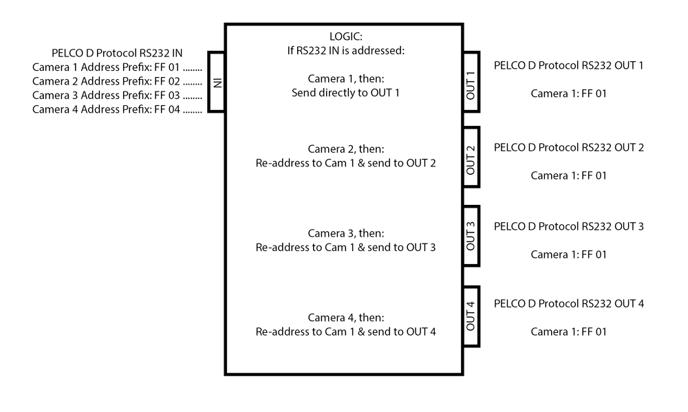
a. Has ONE (1) incoming RS232 port
b. Has FOUR (4) separate outgoing RS232 ports
c. "reads" an incoming RS232 stream,
d. look at the first 2 Bytes of info
e. check for the "address" (2nd byte)
f. if it is addressed "FF 01 .........", forward the complete original data out PORT 1 ONLY
g. if it is addressed "FF 02 ........." re-address the data to "FF 01 ........" and forward the complete data out PORT 2 ONLY
h. if it is addressed "FF 03 ........." re-address the data to "FF 01 ........" and forward the complete data out PORT 3 ONLY
i. if it is addressed "FF 04 ........." re-address the data to "FF 01 ........" and forward the complete data out PORT 4 ONLY
Attached is a drawing of this for those who are more "visual" like me.
The baud rate is 9600, 8, N, 1 (no flow control), if that helps.
Is this possible with the parallex? (i've been advised elsewhere this may be the best choice for what I want to achieve)
If so, would anyone be willing to "tutor" me in learning how to get this done?
If not, would anyone be able to suggest a more suitable platform to achieve it?
This is what I know about the Pelco D protocol (thanks to CommFront - http://www.commfront.com/RS232_Examples/CCTV/Pelco_D_Pelco_P_Examples_Tutorial.HTM )
The format of Pelco-D
Pelco-D consists of 7 hexadecimal bytes (all byte data used in this page are in Hexadecimal format unless otherwise specified).
Byte 1 Sync
Byte 2 Camera Address
Byte 3 Command 1
Byte 4 Command 2
Byte 5 Data 1
Byte 6 Data 2
Byte 7 Checksum
Byte 1 (Sync) - the synchronization byte, fixed to FF
Byte 2 (Camera Address) - logical address of the camera being controlled (Address 1 is 01)
Byte 3 & 4 (Command 1 and 2) are shown below
Byte 5 (Data 1) - pan speed, range from 00 (stop) to 3F (high speed) and FF for "turbo" speed (the maximum pan speed that the device can go)
Byte 6 (Data 2) - tilt speed, range from 00 (stop) to 3F (maximum speed)
Byte 7 (Checksum) - sum of bytes (excluding the synchronization byte), then modulo 100 (Decimal code: 256)
Command 1 and 2 details
Bit 7 Bit 6 Bit 5 Bit 4 Bit 3 Bit 2 Bit 1 Bit 0
Command 1 Sense Reserved Reserved Auto / Manual Scan Camera On/Off Iris Close Iris Open Focus Near
Command 2 Focus Far Zoom Wide Zoom Tele Tilt Down Tilt Up Pan Left Pan Right Fixed to 0
Example (Command 2):
Pan Left - 0 0 0 0 0 1 0 0, which equals to 04 (both hexadecimal and decimal)
Some other commands
Command Byte 3 Byte 4 Byte 5 Byte 6
Go to Preset 00 07 00 01 to FF
Set Zoom Speed 00 25 00 00 to 33
Set Focus Speed 00 27 00 00 to 33
Alarm Ack. 00 19 00 Alarm no.
Pelco-D command string examples
Camera Address: 1
Pan Left at high speed: FF 01 00 04 3F 00 44
Pan Right at medium speed: FF 01 00 02 20 00 23
Tilt Up at high speed: FF 01 00 08 00 20 AF 27
Tilt Down at medium speed: FF 01 00 10 20 00 31
Stop all actions (Pan/Tilt/Zoom/Iris etc.): FF 01 00 00 00 00 01
Note: there will be no response from cameras in Pelco-D protocol
Many thanks in advance,
duBe
I have no experience at all with micro controllers & only brief experience with wiring up electronics / & some low-level programming, so please accept my apologies up-front.
I have a need to create a device that:
a. Has ONE (1) incoming RS232 port
b. Has FOUR (4) separate outgoing RS232 ports
c. "reads" an incoming RS232 stream,
d. look at the first 2 Bytes of info
e. check for the "address" (2nd byte)
f. if it is addressed "FF 01 .........", forward the complete original data out PORT 1 ONLY
g. if it is addressed "FF 02 ........." re-address the data to "FF 01 ........" and forward the complete data out PORT 2 ONLY
h. if it is addressed "FF 03 ........." re-address the data to "FF 01 ........" and forward the complete data out PORT 3 ONLY
i. if it is addressed "FF 04 ........." re-address the data to "FF 01 ........" and forward the complete data out PORT 4 ONLY
Attached is a drawing of this for those who are more "visual" like me.
The baud rate is 9600, 8, N, 1 (no flow control), if that helps.
Is this possible with the parallex? (i've been advised elsewhere this may be the best choice for what I want to achieve)
If so, would anyone be willing to "tutor" me in learning how to get this done?
If not, would anyone be able to suggest a more suitable platform to achieve it?
This is what I know about the Pelco D protocol (thanks to CommFront - http://www.commfront.com/RS232_Examples/CCTV/Pelco_D_Pelco_P_Examples_Tutorial.HTM )
The format of Pelco-D
Pelco-D consists of 7 hexadecimal bytes (all byte data used in this page are in Hexadecimal format unless otherwise specified).
Byte 1 Sync
Byte 2 Camera Address
Byte 3 Command 1
Byte 4 Command 2
Byte 5 Data 1
Byte 6 Data 2
Byte 7 Checksum
Byte 1 (Sync) - the synchronization byte, fixed to FF
Byte 2 (Camera Address) - logical address of the camera being controlled (Address 1 is 01)
Byte 3 & 4 (Command 1 and 2) are shown below
Byte 5 (Data 1) - pan speed, range from 00 (stop) to 3F (high speed) and FF for "turbo" speed (the maximum pan speed that the device can go)
Byte 6 (Data 2) - tilt speed, range from 00 (stop) to 3F (maximum speed)
Byte 7 (Checksum) - sum of bytes (excluding the synchronization byte), then modulo 100 (Decimal code: 256)
Command 1 and 2 details
Bit 7 Bit 6 Bit 5 Bit 4 Bit 3 Bit 2 Bit 1 Bit 0
Command 1 Sense Reserved Reserved Auto / Manual Scan Camera On/Off Iris Close Iris Open Focus Near
Command 2 Focus Far Zoom Wide Zoom Tele Tilt Down Tilt Up Pan Left Pan Right Fixed to 0
Example (Command 2):
Pan Left - 0 0 0 0 0 1 0 0, which equals to 04 (both hexadecimal and decimal)
Some other commands
Command Byte 3 Byte 4 Byte 5 Byte 6
Go to Preset 00 07 00 01 to FF
Set Zoom Speed 00 25 00 00 to 33
Set Focus Speed 00 27 00 00 to 33
Alarm Ack. 00 19 00 Alarm no.
Pelco-D command string examples
Camera Address: 1
Pan Left at high speed: FF 01 00 04 3F 00 44
Pan Right at medium speed: FF 01 00 02 20 00 23
Tilt Up at high speed: FF 01 00 08 00 20 AF 27
Tilt Down at medium speed: FF 01 00 10 20 00 31
Stop all actions (Pan/Tilt/Zoom/Iris etc.): FF 01 00 00 00 00 01
Note: there will be no response from cameras in Pelco-D protocol
Many thanks in advance,
duBe

1000 x 599 - 93K
Comments
This would be almost trivial to do with the Propeller.
You'll need appropriate RS-232 converter chips but the software should be pretty simple.
Here's a serial port merger which went the other direction.
https://forums.parallax.com/discussion/comment/1030339/#Comment_1030339
It had four inputs on one output (IIRC).
Do you need the checksums recalculated? Do they need to be tested on the input?
If either of these requirements are needed the program will require a bit more work but it still shouldn't be problem for the Propeller.
I think a Propeller Project Board would be your best choice for hardware.
We can help you choose the appropriate RS-232 chips if you need it.
+ 1. Easy project for the propeller to handle.
Yes, the checksum needs to be recalculated, here's some advice I received about doing that:
**
Little state machine to know if it's in/out of sync.
Wait for the sync byte, check the overall framing, ie sync thru checksum
Sequence through bytes as received, redirect to appropriate output port, change ID, and goose the checksum as that goes out to reflect the change in ID earlier.
So from 2 to 1, add -1 to the sum, 3 to 1 add -2, etc
**
Any advice you can give me about what chips / hardware I need to get would be GREATLY appreciated.
I'll have a look at the project you mentioned & try to understand it.
Sorry if I posted this in the wrong area though, I honestly thought I did post it to the PROPELLER PROJECT BOARD, but it seems I got myself confused (I seem to do that a lot).
Many thanks,
duBe
I'll add my suggestion of a RS-232 chip. I've read you don't really need one to receive RS-232 signals but I've always used them myself.
What kind of connectors will you need?
The checksums make this project a bit harder but it's still pretty simple.
Sorry Duane, see how easily I get myself confused?
I understand about the PROPELLER PROJECT BOARD now (hardware not forum board) - gotta have a laugh right?
There are 2 different camera controllers (these outputs the RS-232 with the multi-camera addressed commands) that I can use:
1. has a standard male D9 connector
2. has a terminal block connector with the Tx / Rx etc terminals that just auto-crimp the wires as you slide it in to the block
The cameras have standard female D9 connectors for the RS-232 input.
So I guess the device I want will just need to have:
a. ONE (1) x standard female D9 RS-232 input
b. FOUR (4) x standard male D9 RS-232 outputs
I can then just make up 2 different interface cables for between the controllers :
c. Standard female D9 to standard male D9
d. Fly-lead to standard male D9
Does that make sense?
Cheers,
dube
https://www.sparkfun.com/products/589
SparkFun no longer sells the DIP version of the chip but you could use the surface mount version on the Propeller Project Board.
Each chip has two input and two output so you'd probably need two chips.
The chips require 0.1uF caps.
Parallax, SparkFun and lots of other places sell D9 connectors.
From just the information above, I wrote a simple program to do what you described. It has no error checking, so if you send a command to camera 5, it will be lost if you don't have more than 4 ports connected. But you could use this for up to 15 output ports and one input port, as-is.
The BS2 can handle incoming RS232 with just a 22k ohm resistor in series with the input pin. The output will go 0-5V which may be enough for the cameras if they are close. If not, you'll need some kind of a line driver to boost the signal.
Any serial data arriving while the BS2 is sending will be lost. It would be a lot easier to miss the sync byte and the "turbo" command could end up being interpreted as the sync.
If each serial command had a consistent delay (long enough for the BS2 to send the last command), then the BS2 could do the job (though at a higher price).
If serial commands arrive close together then the BS2 would likely miss many of the commands.
I'm sure thankful you both have taken so much time to help me so far.
Sapphire:
I read the code you included ( now bearing in mind I'm actually a simple old motorcycle mechanic) I kind of understand some of if, but mostly not.
However, the thing that struck me was how "simple" it looks, it really looks more like a "thought process".
I'm not sure what I was expecting really, but despite not understanding it, I'm impressed that such a "simple" looking block of code could do all of what I wanted.
Nice!
Duane:
Thanks for the "heads-up" about the reading v's writing conflict on the BS2 module's RS-232 (I've gotta admit though, I don't know what a BS2 module is).
If it's a simple "once-only" command (let's say "goto preset 01") then I guess that wouldn't present a problem, because in the real-world, you wait for the camera to respond to that command before doing anything else.
However, I suspect if I hold down a PTZ control button on the camera controller (let's say "zoom in") for some time, I am guessing the command is sent out continually / repeatedly until I release the button.
I only guess that because that's the effect I see on the camera if I do hold down a PTZ control button.
I don't know if there are any "pauses" between these continuous / repeated commands ( I suspect there is a TINY pause ) but I'm guessing you're suggesting any pauses may not be long enough for the BS2 module to finish sending out the converted RS-232.
So, all that considered, where do you suggest I start?
Many thanks,
duBe
https://www.parallax.com/product/bs2-ic
It requires some sort of carrier board such as:
https://www.parallax.com/product/27130
The Propeller Project Board uses the Propeller microcontroller.
The Propeller has 8 "cogs" or processors and can do multiple things at once (listening on a serial at the same time as sending a serial signal).
I have links to Propeller tutorials in post #3 of my index (see my signature).
When/if you're ready to start ordering supplies, you're welcome to post what you intend to get here and we could offer our thoughts on your selections.
That said, yes the sync byte could be lost, but I did not include any error checking for that in an attempt to show the simplicity of the program. A few more lines of code will catch that and discard those command. Seven bytes at 9600 bps is only 7ms and I doubt you would press and release the button in less than 15ms. But even if you did, just move the control again to send another start/stop sequence.
This is just one example of how to tackle the problem. I use the propeller for a lot of projects, but for a beginner, I though this would be an easier approach to understand.
thanks again for all the advice, I REALLY do appreciate it.
Sapphire:
Thanks for the info about how the commands are organised, I didn't know there was a STOP command, that's interesting really.
So, if the "READ IN" missed the STOP command, would that cause the camera to continue forever, unless another command is sent & the STOP command after that is received?
I ask that because I have noticed a few times that a camera "runs-away" on say PAN or TILT & I need to send it a new command in the opposite direction to get it to STOP.
Duane:
Thanks HEAPS for the info about the difference in technologies & how they are used.
I think I'd like to try both ways of doing it for the reason of learning both technologies.
I'm going to buy the BS2 module together with the relevant Super Carrier Board for the BS2-based project - is there anything else I'll need to buy for this project (like the 22KΩ resistor)?
I'm also going to buy the Propeller Project Board for the Propeller-based project - is there anything else I'll need to buy for this project (like the 2 x MAX3232 chips)?
Many thanks in advance,
Andy
that makes sense now, I didn't really know what was going on until now.
Ok, here's my "shopping cart" for Parallax:
Does that look right for these 2 options?
Cheers,
duBe
You don't need a separate Propeller chip. The Project board comes with the chip installed.
When I first started learning about microcontrollers I purchased both Basic Stamps and a Propeller board. I hindsight, I wish I would have saved the money on not purchased the Basic Stamps.
I personally don't see a need to get a Basic Stamp.
My suggestion would be to get two Propeller Project boards and none of the other items. You might want to get five Project boards to get the $20 price.
I doubt everyone will agree with my suggestion (which is absolutely fine).
BTW,. Sapphire, I think your BS2 example was great and you're probably right that the BS2 would work for this project. However, I think the BS2 has very poor performance for its price.
Duane, thanks and I agree the BS2 cost is much higher for its performance. I only suggested it because I think it would be easier to get started without having to learn SPIN, figure out all the 4-port-serial routines and put it all together. But if you're up for it, it will certainly work.
The thing I missed the most when moving from the BS2 to the Propeller was the BS2's build in serial commands. Still you don't even need to use a 4-port object to do this in Spin.
I think this does the same thing your PBASIC program does.
CON

  _clkmode = xtal1 + pll16x
  _xinfreq = 5_000_000

OBJ

  Serial[5] : "Parallax Serial Terminal"

PUB Main | inputCharacter, portNumber

  Serial[0].StartRxTx(0, 10, 0, 9_600)
  Serial[1].StartRxTx(11, 1, 0, 9_600)
  Serial[2].StartRxTx(12, 2, 0, 9_600)
  Serial[3].StartRxTx(13, 3, 0, 9_600)
  Serial[4].StartRxTx(14, 4, 0, 9_600)

  repeat
    repeat
      inputCharacter := Serial[0].CharIn
    until inputCharacter == $FF

    portNumber := Serial[0].CharIn
    Serial[portNumber].Char($FF)
    Serial[portNumber].Char($01)

    repeat 4
      inputCharacter := Serial[0].CharIn
      Serial[portNumber].Char(inputCharacter)

    inputCharacter := Serial[0].CharIn
    Serial[portNumber].Char(inputCharacter - portNumber + 1)
There's still one cog to spare.
As you mentioned with your code, it would benefit from some error checking. I think PBASIC wins at looking simpler but, the Propeller version would not miss any messages if they came close together.
I'll roll with that advice Duane, I guess considering I'm ordering stuff from the US to be delivered in AU, getting a few of them will make it easier for me to get going with other projects in the future as well.
Cheers,
duBe
That's a very nice and easy to understand bit of code for passing the data along, but I don't see where the new checksum is calculated and inserted in the data stream. I know it's just me and my "waste not, want not" attitude, but I don't like to see five cogs used for something that could be done with one. Since no data is coming back from the cameras any one of the four rx lines could be used for the incoming data, so only a single instance of the four port object is needed. That leaves more resources for other functions to be added.
You're of course right about there being much better ways to do this. The idea was to make it look as simple as I could.
The new checksum is calculated in the last line of code. I think the code replicates the code written by Sapphire for the BS2.
I personally think it would be a good idea to check the checksum as the data comes in and only send on valid commands.
BTW, I miscounted the cogs. There should be two which aren't used.
As you suggest, this could easily be done with just two cogs rather than six.