Controlling my Contour camera
I would like to control my Contour camera with a propeller but I can not figure out
how to bypass the magnetic switch it uses to start/stop recording.
It has a switch diagram on the PCB which gave me hope that I could just wire into
two solder points to bypass the magnetic switch but that didn't work.
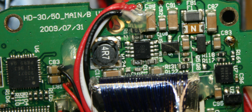
It has another component on the board with a N on the back (polarization?)
Could anybody point me to what a magnetic switch looks like?
Thought I might try a electric magnet or servo with a magnet on arm, but both seem overly cumbersome.


Comments
A Hall-effect switch could simply look like a transistor in a TO-92 package or surface mount package... they come in both. The require 3 wires; two for power and one for switching (likely an open-collector or open-drain design).
The N you mention might indicate that is the switch and that is responds to the North of a magnet. Hall-effect devices can switch in several ways - some latch, others just pulse, some need both the N and S of the magnet to fully work and others just need one end.
Your photos are not comprehensive, so they don't really tell me much. This is a reverse engineering project and that usually starts with a strategy planning session. You might try passing a magnet over the powered up board to locate your switch. Or you might look at the actual context of chassis and board to locate where the magnetic switch is supposed to be. You haven't provided any photos of a chassis.
Hard to say how successful you will be. Much depends on a lot of tedious communication and getting up to speed on a wide variety of topics at the same time.
https://www.google.com.tw/search?q=contour+camera+taken+apart&tbm=isch&tbo=u&source=univ&sa=X&ei=Iw_yVKqYAcT38QX83YGQBg&ved=0CCQQsAQ&biw=1024&bih=380
I can look around for more. There tend to be people that hack just about anything these days then photo document what they discover. This might save you a lot of time and trouble. It may also prevent some serious damage.
https://www.youtube.com/watch?v=lobQf8ieQfM
it difficult to lay-out and get a full picture of.
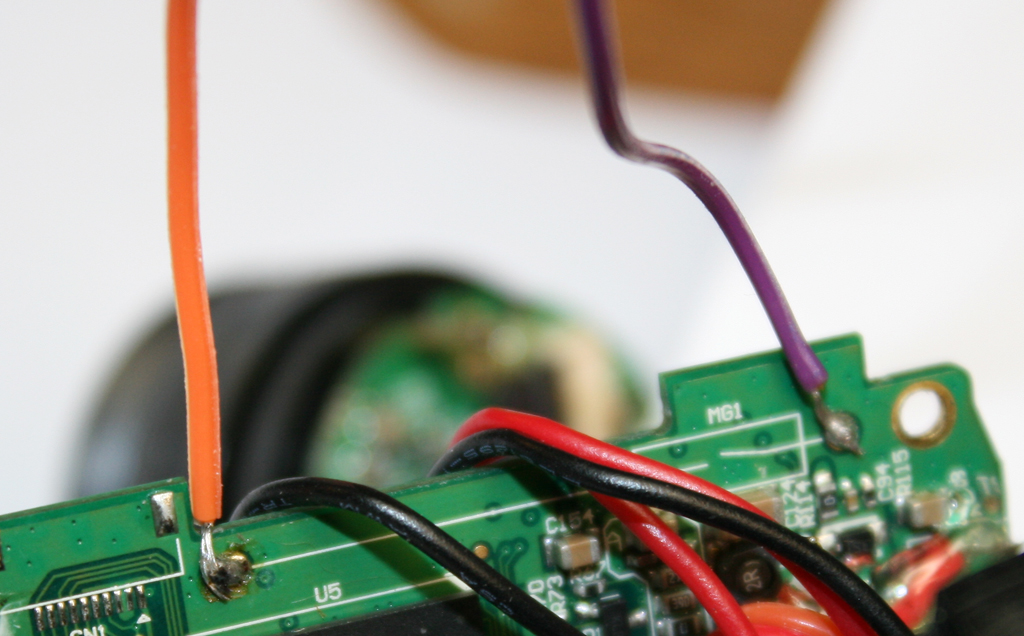
The picture were I soldered on a orange and purple wire is of the top of the board. The magnet slides from
orange wire to purple wire to turn on recording. The magnet rest over the switch diagram marked MG1.
Looked on board for MG1 and could not find so I am as assuming it is just referencing the switch magnet.
Straight underneath there on that side looks to be three caps as they are numbered C#. On the other side
is an IC and a three pronged transistor? Looks like I was playing there last time I was fooling with it as it looks like it has
seen better days.
Also, does it still turn on using a magnet? If not, can you undo what you did and make it do so?
You are giving us a snapshot of your situation, we need something more like a story.
Okay... is it possible that the reed switch is a normally closed type? If that is the case then connecting those two wires would do nothing. You would need to remove the reed switch to make it work.
It makes more sense to me for it to be a normally open type switch but what do I know...
Something the camera still works as looking at it up close it looks overheated.
It's been nearly two years since I played with it. I can't remember what I tried.
Would the switch pins be the two on the same side of the chip?
I'm having a hard time understanding you.
If there is a reed switch, and it sounds like there is, then it should be dead simple to get it to work, but it sounds like you are saying that it hasn't worked in two years? When was the last time the camera operated normally?
The camera does work with a magnet. It has been two years since playing with it the last time. I tried to find the switch then but could not.
Google images of smd reed switches show several different looks. The three prong transistor looking one (last picture I uploaded) is right under where the magnet rest but looks
like (memory is bad) that I took that out and put it back. So I probably tried that connection to bypass the reed switch.
If I had a smaller magnet I could pinpoint it better I guess. I come anywhere close to the front half of board it triggers, so I can't isolate a single area.
So now I am pretty sure it is the reed switch, not sure why I haven't been able to bypass it by directly connecting points.
If it is normally closed then that could be what was keeping me from making it work as I have just been trying to close the connection.
What I am trying to find out is if it worked recently. Did you test to see if it works before modifying it today? Last night?
Judging by the hole spacing, and the fact that there are holes - I would think that the reed switch was a through hole type. A photo of the other side of the board should answer this question.
The holes are empty so I see that there never was a reed switch in that place. I'm guessing that U2 is a hall effect sensor. I would pass a magnet over it while monitoring what the pins do, then you will know what it takes to activate it.
Or at least it did before I just now removed that part. It turns on and off but won't start recording
even introducing a magnet.
So I am pretty sure that is the switch, but worried right now it might not just be a reed switch but
a hall effect sensor. The camera might be looking for something more specific (signal) then the connection
of two points which still doesn't work for me.
http://www.mouser.com/ds/2/196/TLE4961-2M_FinalDS_Rev1-360223.pdf
Right. that is where I was trying to add my own switch to bypass the switch on the board.
I agree, I would replace the chip then use a multimeter on each pin while activating it to see what kind of signal it needs. If you have an oscilloscope, all the better - but maybe not necessary.
I replaced the hall effect sensor and soldered two wires to the ground and out pins so
that I could more easily check them with the multimeter. Mine has been on the fritz (measuring 9volts for 3volts)
and it didn't show a current even when the camera was recording with the magnet.
I accidentally let the two wires connect and BAM, it started recording.
That is likely an open-collector switching device that makes the idea of switch a bit more complex. Open-collector (and open-drain) devices normally are pulled to the V+ and when the magnet passes over them, they are pulled to GND. Somewhere else on the board many read the signal and invert it (in the microcontroller or in a inverter chip)
As I said before, there tends to be a lot of subjects that have to be learned at the same time to get up to speed.
I never really thought the device would have a reed switch. Too easy to bounce contact and cause problems. Modern products desire hall-effect switches.
I did see where you soldered the wire and saw markings that read MG1 never what appears to be a switch icon. That all may have been a provisional board design that was never used. Manufacturers are very frugal. So they will order a board for production that has several alternative designs on the one board. If parts are unavailable or the cheapest configuration doesn't work right, they can use the same board for their Plan B.
Having more than one design on a board and empty component pads can be confusing.
Now that you have the hall-effect switch removed, then resolder, AND accidentally touched the other switch wires together, it records... right? That seems to say there are indeed two designs for switching on the board.
And you may have gotten very very very lucky to find this. You are taking risks without fully understanding the board circuitry... all sorts of bad thing might happen.
+++++++++++
How do you desire to use the Propeller? Is the board 3.3V logic or 5.0V logic? You need to tell us what you hope to achieve, and please go slow.
The wonderful thing here is that open-collector/open-drain works quite nicely with two switches in parallel.
____________
Having said that, I am not sure what the two wires at the top edge of the board are doing or if they are needed any longer. You might be able to do all this with two wires taken off the hall-effect device. If you still need the other two wires, we need to ponder why.
So it should be 1 from prop pin to record (activate optocouper/connect pin to ground) and zero to stop recording.
I wished the thru-holes from the legency design worked as it was easier to solder into then the smd pins of the hall effect sensor.
You seem to have a slide atop the camera case that is used to turn the record on/off. That slide may hold a small magnet that just sits over the hall-efffect sensor to keep the device on.
Is the power button a separate switch? Is it in a different location? That may be a conventional on/off switch.
The Propeller can just take the signal and accept OFF as a LOW and ON as a HIGH condition.
Actually the optocoupler is extemely handy fo insertion in parallel with an open-collector and eliminates all sorts of hassles with conforming to the needs of the camera's power versus the needs of the Propeller's power.... even the grounding can be separate.
I am going offline now. It is 3:35am here in Taiwan.
It is hard to say what the through-hole are intended for. It could be that they too are open-collector in parallel to the hall-effect switch and merely intended to bench test the record function.
Test benches often use a 'spike board' that interfaces with holes in the boards nowadays. We have been commited to surface mount for decades now. So I doubt any real component was intended in this design.