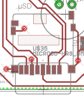
How bad is this uSD routing gaffe?
I made this embarrassing error on my order of 25 PCB boards:

I ran a trace to the rightmost pad (pin#1, DAT2) instead of the pin next to it (pin#2, CS).
I had it right on a previous version but messed it up trying to change what Prop pin things went to...
Anyway, I'm trying to decide if this error is bad enough to warrant buying new boards...
I can fix it with a solder bridge between pins #1 and #2 on the board.
This seems to work and hasn't yet damaged my uSD card (as far as I can tell anyway).
Anybody know if this solder bridge is safe?


Comments
That pin is reserved in SPI mode and since you manage to get it into SPI mode I guess that operation was safe. If I were in doubt I would measure the supply current during initialization to confirm that there is no conflict. You could alternatively scope CS signal to make sure it is level and clean as any I/O conflicts would should up as straying logic levels.
I'm surprised you managed to wire to the wrong pin as even though I manual route my pcbs, I always do netlist checks from the schematic which will warn me if something doesn't match up. Sometimes I will start placing main components on a pcb before I do a schematic just to get a feel for it but then comes the schematic. I used to lay out pcbs from my head changing things on the fly but I'd been bitten too many times with that one tiny little routing error and some were unrecoverable, although some were pcb fabs fault like mixing text on mechanical layers into copper layers!
EDIT: seeing kwinn's post I'd be tempted to cut the pin off the connector before you place it, even cleaner!
I had it working in an earlier version, but I had to do "start_explicit(0,1,3,2)" with FSRW instead of just start(0).
So, I rewired it to be in the usual configuration. Somehow in that process, I messed it up.
Probably because I'm using a borrowed Eagle model for the uSD card that identifies the pins by their SD labels and not SPI labels and I don't always remember what is what.
Anyway, this may be a tough call for me... I've been working on this board for almost a year now and want it to be perfect.
But, if this is the only problem and a solder bridge fixes it, it seems hard to justify the expense...
On the other hand, not sure that it's safe, just because it didn't fry my uSD card.
Checking the current draws is a good idea, I can do that to make sure there's nothing horrible going on...
Maybe that's a better approach... Makes it perfectly safe...
Still, I sorta hope I find another problem with these boards so I can feel better about getting new ones...
-Phil
But, I don't think any program could have prevented the dumb mistake I made here...
There are a couple of very nice things about Eagle though:
1. Sparkfun posts most of their designs for their boards, done in Eagle. So, there's a large library of designs you can borrow from.
2. I can post my design files and people can view/modify them and make their own version if they want to for free.
That said, there are many quirks about Eagle that I'm not fond of... It isn't the most intuitive CAD tool...
-Phil
Do you find CADINT libraries are current. Are they kept up to date?
-Phil
Sandy