

Propeller Activity board C Compass project

Ok, you purchased one of those HMC5883 device so you could build a compass module. After you got it setup and working and looked at the sample code you were more confused than when you started. What does X, Y, and Z have to do with North, South, East and West.
So after you were done Spinning your wheels it's time to C what really can be done.
This project will get the HMC5883L working on a flat surface taking out the complex angle calculations need for that environment. Using the sample code provided you will be able to spin the compass in a circle that will give you the offsets you need to make the calculation work for determining what heading the compass is pointing too.
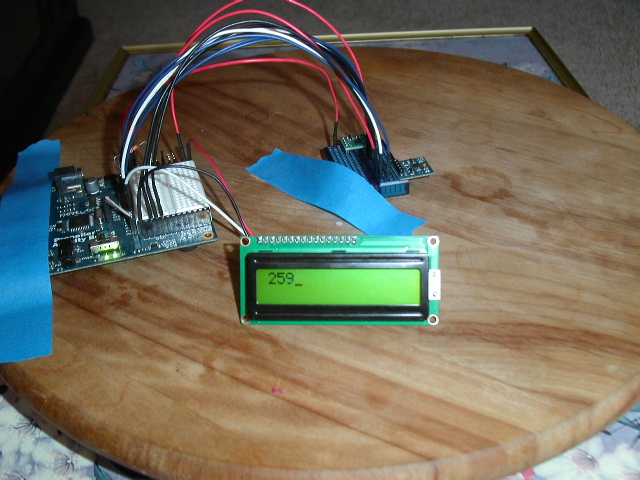
In addition there is code that will display the heading on the Parallax LCD display if you choose too.
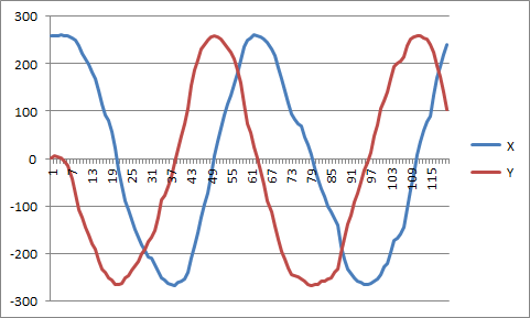
As you spin the compass in a circle the program will output the X, Y, and Z values that you can later plot on a graph that will look like the documentation for the chip. You will see that because of metal near or around your environment that the plots will be off in one direction or another. This is where the offset comes in. This will put the plot axis back to zero so that when you use the Arc Tangent you will get the correct heading instead of some strange value.
What you will need is the HMC5883 chip along with a turn table to mount the unit on so you can slowly turn the compass in a circle. As you turn the compass a reading will be taken every quarter of a second. These reading will determine the largest X, Y, and Z value along with the smallest X, Y, and Z value. It will then give you those numbers as an offset that can be put back into the program. This will fix the calculations so that the correct heading will show on the LCD display.
To install the code you will need to create a folder called "Custom" in the learn/simple libraries folder. Inside there you will unzip the two libraries called libcompass.zip and liblcddisplay.zip. In your My Projects folder you will unzip the compass.zip file that contains the sample code. You will run this code to display the results of turning the turn table in a circle. You will need to connect the chip with the LCD using pin 3 and the compass using ping 4 for Clock(SCL) and 5 for Data(SDA).
Next step will be to use the accelerometer to calculate the heading when the chip is not level.
Mike
liblcddisplay.zip
libcompass.zip
Compass.zip

So after you were done Spinning your wheels it's time to C what really can be done.
This project will get the HMC5883L working on a flat surface taking out the complex angle calculations need for that environment. Using the sample code provided you will be able to spin the compass in a circle that will give you the offsets you need to make the calculation work for determining what heading the compass is pointing too.
In addition there is code that will display the heading on the Parallax LCD display if you choose too.
As you spin the compass in a circle the program will output the X, Y, and Z values that you can later plot on a graph that will look like the documentation for the chip. You will see that because of metal near or around your environment that the plots will be off in one direction or another. This is where the offset comes in. This will put the plot axis back to zero so that when you use the Arc Tangent you will get the correct heading instead of some strange value.
What you will need is the HMC5883 chip along with a turn table to mount the unit on so you can slowly turn the compass in a circle. As you turn the compass a reading will be taken every quarter of a second. These reading will determine the largest X, Y, and Z value along with the smallest X, Y, and Z value. It will then give you those numbers as an offset that can be put back into the program. This will fix the calculations so that the correct heading will show on the LCD display.
To install the code you will need to create a folder called "Custom" in the learn/simple libraries folder. Inside there you will unzip the two libraries called libcompass.zip and liblcddisplay.zip. In your My Projects folder you will unzip the compass.zip file that contains the sample code. You will run this code to display the results of turning the turn table in a circle. You will need to connect the chip with the LCD using pin 3 and the compass using ping 4 for Clock(SCL) and 5 for Data(SDA).
Next step will be to use the accelerometer to calculate the heading when the chip is not level.
Mike
liblcddisplay.zip
libcompass.zip
Compass.zip


Comments
Mike, I think if you can take a reading while the sensor is level, you can use this initial reading to find the how far from horizontal the magnetic field is. You can find the difference between this initial "tilt" and the current "tilt" to determine how far your sensor is from being level.
I don't have a video of the working version, but I used these servo controlled gimbals to keep the HMC5883L sensor level. The video in the thread didn't work very well since I had the sensor too close to the servos. Once I raised the sensor a few inches away from the servos, the contraption worked much better (I need to make a video of the improved version).
By using all three axes of the sensor, I think you can calculate the heading even when the sensor is tilted.
Mike
I think you're right. There's a cone shaped surface which should give the same magnetometer reading. I look forward to seeing what you come up with when using an accelerometer.