

Something is wrong with my design, please help
 Borna
Posts: 36
Borna
Posts: 36
Hello all
I have a serious problem which I am not sure how to handle this. Part of the issue is I am not really expert at electronic components.
I have a small engine that I want to control the PRM and keep it between 1600– 1200 using solenoid and Basic stamp II. This engine uses CDI ignition with 6 volt battery to provide spark to the spark plug.
Here is the example of CDI I am using
http://www.hobbyking.com/hobbyking/store/__10996__replacement_cdi_ignition_for_rcg_50cc_engines.html
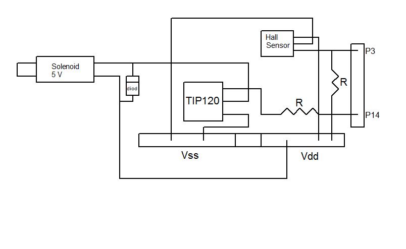
As you can see from the diagram (tip.jpg), I am using basic stamp II to activate/deactivate a solenoid base on the RPM of a flywheel.
A small magnet is attached to the flywheel, and the hall sensor detects the number of pulses in 5000 milliseconds when the magnet pass by the sensor. Based on that, the stamp calculate the RPM of the engine. If the RPM is greater than 1600 then the solenoid is activated a keep the exhaust valve opened until the RPM is dropped below 1200.
Here is the code for the logic.
Everything works without an issue as long as CDI is not connected to generate spark. I can use a RC electric starter to turn the flywheel and using the debug statements, I can see the logic works as designed. The solenoid gets activated as soon as RPM reaches 1600 and deactivated once below 1200.
However the issue is that the basic stamp is stop working when I connect CDI to the battery and when the first spark is generated.
By stop working I mean the basic stamp no longer activate the solenoid and the debug screen is hung until I press the reset button on the stamp, and hung again as soon as the first spark is generated.
The CDI is a unit by itself and 100% independent of the stamp.
Also what I noticed is while the ignition is on and generates sparks, and if the “collector” on the transistor is disconnected, then the stamp works and the debug shows the PRM on the screen, but of course the solenoid is not working since I discounted from the collector. So basically the unit will not crash /hang.
Can someone help me identify the problem? Is my wiring correct or I am missing something?
Am I using a right transistor for this project? I tried to put a diode between collector and solenoid and still didn’t work.
here is my code
' {$STAMP BS2}
' {$PBASIC 2.5}
Gov PIN 14
SpeedIn PIN 3
SensorPulses VAR Byte
rpm VAR Word
GovFlag VAR Bit
GovFlag = 0
DO
rpm = 0
SensorPulses = 0
Capture CON 500
COUNT SpeedIn, Capture, SensorPulses
rpm = (SensorPulses * 120)
DEBUG CR, "Pulses = ", DEC SensorPulses
DEBUG CR, "RPM = ", DEC rpm
IF rpm > 1600 THEN
DEBUG CR, "ON "
HIGH Gov
ENDIF
IF rpm < 1200 THEN
DEBUG CR, "OFF "
LOW Gov
ENDIF
LOOP
I have a serious problem which I am not sure how to handle this. Part of the issue is I am not really expert at electronic components.
I have a small engine that I want to control the PRM and keep it between 1600– 1200 using solenoid and Basic stamp II. This engine uses CDI ignition with 6 volt battery to provide spark to the spark plug.
Here is the example of CDI I am using
http://www.hobbyking.com/hobbyking/store/__10996__replacement_cdi_ignition_for_rcg_50cc_engines.html
As you can see from the diagram (tip.jpg), I am using basic stamp II to activate/deactivate a solenoid base on the RPM of a flywheel.
A small magnet is attached to the flywheel, and the hall sensor detects the number of pulses in 5000 milliseconds when the magnet pass by the sensor. Based on that, the stamp calculate the RPM of the engine. If the RPM is greater than 1600 then the solenoid is activated a keep the exhaust valve opened until the RPM is dropped below 1200.
Here is the code for the logic.
Everything works without an issue as long as CDI is not connected to generate spark. I can use a RC electric starter to turn the flywheel and using the debug statements, I can see the logic works as designed. The solenoid gets activated as soon as RPM reaches 1600 and deactivated once below 1200.
However the issue is that the basic stamp is stop working when I connect CDI to the battery and when the first spark is generated.
By stop working I mean the basic stamp no longer activate the solenoid and the debug screen is hung until I press the reset button on the stamp, and hung again as soon as the first spark is generated.
The CDI is a unit by itself and 100% independent of the stamp.
Also what I noticed is while the ignition is on and generates sparks, and if the “collector” on the transistor is disconnected, then the stamp works and the debug shows the PRM on the screen, but of course the solenoid is not working since I discounted from the collector. So basically the unit will not crash /hang.
Can someone help me identify the problem? Is my wiring correct or I am missing something?
Am I using a right transistor for this project? I tried to put a diode between collector and solenoid and still didn’t work.
here is my code
' {$STAMP BS2}
' {$PBASIC 2.5}
Gov PIN 14
SpeedIn PIN 3
SensorPulses VAR Byte
rpm VAR Word
GovFlag VAR Bit
GovFlag = 0
DO
rpm = 0
SensorPulses = 0
Capture CON 500
COUNT SpeedIn, Capture, SensorPulses
rpm = (SensorPulses * 120)
DEBUG CR, "Pulses = ", DEC SensorPulses
DEBUG CR, "RPM = ", DEC rpm
IF rpm > 1600 THEN
DEBUG CR, "ON "
HIGH Gov
ENDIF
IF rpm < 1200 THEN
DEBUG CR, "OFF "
LOW Gov
ENDIF
LOOP
804 x 494 - 24K
Comments
In regards to the basic stamp stopping, definitely sounds like an
RF (radio frequency) problem. Any sparks generate "white" noise,
which is signals across a large bandwidth. You might begin by
isolating the power supply of the stamp. Grounding may be an issue,
in which I would make sure I have grounded all apparatus, with good
connection. RF loves to make a home in parts that are not grounded.
(floating). Keep me posted on your progress.
Also, don't have anything off-board connected to the Stamp's Reset pin.
Is the 6-volt battery the power supply for the Stamp as well? Going through the 5-volt regulator with only 6 volts available will be marginal. How much current does the solenoid draw?
Make sure the diode on the solenoid is the right way around.
Cheers
Try using a separate 9 Volt battery just for the Stamp (temporarily) to see if everything works as expected. Just make sure you connect the 9 V battery to pin 24 and ground. Refer to the Stamp Manual on proper connection.
The solenoid is small 5 volt from sparkfun.
The power to the stamp is through a 9 volt battery.
The CDI has its own power source. Is not in any way connected to the stamp or consuming power from the stamp.
I have even tried to different setup in a way to provide external power to solenoid and still same behavior.
So the point is if there is an RF issue from spark, then why stamp doesnt hang or crash when the collector is discounted?
Is it possible that the transistor is getting effected by the RF from spark and cause issue? Am I using a right type of transistor?
Yes you are correct. My actual setting is correct, but the diagram is wrong regarding the diode. I wish I had a better understanding of electronics and tools to troubleshoot this issue. As noted by Stamptrol, I will try 0.01 uF capacitor across the Stamp power supply.
Thanks
Borna
Also try a seperate battery or power supply to your solenoid.
This is not a terribly demanding application so there is something else that we are missing. Can you generate a complete schematic?
Cheers,