From hobby to professional
 Laser Developer
Posts: 140
Have you ever wondered what the difference is between that great idea that you sort-of-got-to-work in your garage and those cool high-tech gadgets that everyone wants? Starting out as an enthusiastic amateur, what does it take to go from a pile of hand soldered components to a real production line, making quality products for hundreds of happy customers?
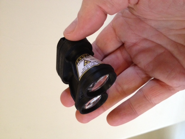
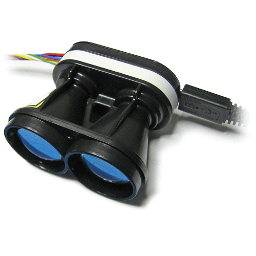
I'm going to use a specific product, the SF10 laser rangefinder, as an example, but everything that you'll see in this post could just as well apply to a fish tank thermostat or an electronic rain gauge that you just know will be a great product one day.
It's probably not the product that will fail you. Instead, it will be something totally unexpected that derails the whole project. So the key to getting stuff to work reliably and repeatably, is to remove the unexpected obstacles. This means that you will need to get organized. Do whatever it takes to keep things neat and tidy. Become obsessed by those little details that can quickly grow into insurmountable problems.
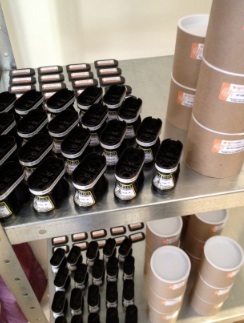
The SF10 production process starts with the packaging and labeling! You may be surprised to learn that packaging and labeling are a crucial part of good design. Trying to figure out where to put that important "DO NOT BREAK THIS BIT" label after you've finished your first prototype is not a good way to make professional products. Go and look at any consumer electronics product and you will notice two common features, nice packaging and detailed labels. We actually design products starting with the operating manual (so we know how it's going to work), labels (because there are legal requirements) and packaging (so we can ship all over the world).
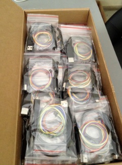
We next make sure that all the accessory items are ready. Almost every product has additional pieces that are separate from the main unit. It may be a cover slip, comms cable, keyboard or just a bunch of small screws. Each SF10 comes with a main connecting cable that carries power and comms as well as a USB cable for configuration. These are sealed in their own bags so that they don't chafe during shipping. These little touches tell the customer that you care about the way they experience your product.
Of course, trying to remember where to put the labels or which accessories are needed will lead to mistakes, so everything is carefully recorded. The list of parts is called a BOM (bill of materials) and the instructions on how to put things together are called Procedures. BOMs and Procedures need to be created during the design process and updated regularly once production begins. Every single part needs to be in the BOM, and every single step in production needs to be accurately recorded in a Procedure.
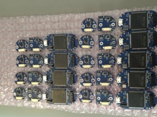
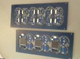
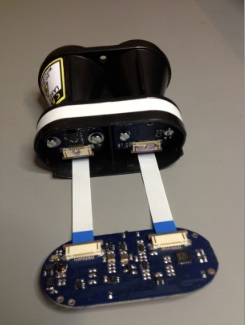
Circuit boards arrive at our factory already populated with electronic components and in panels. You'll notice that there is more than one type of board in each panel. In fact, there are three complete sets of SF10 electronics in each panel, with each set made up of a controller board, a laser board and a detector board. Mixed panels like these are quite common and a great way to prototype several different boards at once without paying for multiple origination costs. In a production situation, it's a good way to make sure that you always have matching sets of boards. These boards are 0.8 mm thick and have four layers of copper, two sandwiched inside the PCB material. They're pretty complicated and took almost a year to design. The laser and detector boards are about the size of your thumbnail.
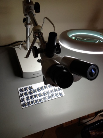
This next Procedure is the one that has the greatest impact on product consistency. For a production line to work effectively, every part that arrives at a particular point in the assembly process must work correctly. We spend a lot of time inspecting perfectly good circuit boards under a microscope. We know the boards will work but we're looking for that unexpected thing that I mentioned earlier. It could be a missing part, a dry solder joint, a "tomb-stone" decoupling capacitor, things that won't stop the unit from working, but might lead to loss of performance, long term failures or intermittent faults. Inspections take a lot of practice to do correctly. You need to be very critical about everything in your products, and recognize that every imperfection is important.
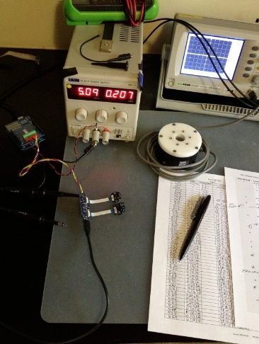
There should always be a number of "jigs" and test Procedures used to test each board or set of boards. The testing "protocol" can take a long time to perfect, at least 100 finished products. In the picture above there is a current limited power supply (never use anything else), a 'scope, a small automated test jig, a laser power sensor and two important documents, the test Procedure and the test results. We use paper in addition to automatic computerized record keeping because the FDA requires us to keep these records safe for many years.
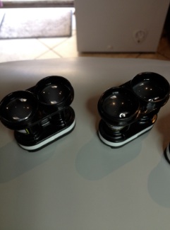
Mechanical assembly runs in parallel with the electronics testing, so that once the boards are ready, there is a completed housing waiting. This method of separating out the production processes into different pathways forms part of the vast subject called "production management". Don't underestimate how difficult it is to get all the right parts in the right place at the right time.
Surprisingly, the arrival of the finished product is something of an anti-climax after the intense concentration and discipline of the production Process. When done correctly, the rate of failures and the number of hold-ups will decrease as the components progress along the production line, so the final product should work first time. This may be the fundamental difference between a hobby project and a professionally engineered product, but there is only one true measure of how well you are making a product, and that is feedback from your customers. Listen to them. Don't argue. Fix problems as fast as you can. Remember that they are the ones with the money, and without them, your product is just another idea.
I hope you enjoyed reading this story. LD


Comments
Yes, very much. Thanks for posting this.
I've very curious about the SF10.
I have one of your SF02 sensors from Parallax on my latest robot.
I'm very impressed with it so far.
The SF02 is a very important product for us because it has allowed people to do experiments that previously would have been way too expensive. We use feedback from our customers to determine which direction to evolve our products, and the SF10 is a result of a request from one of our SF02 customers, Joe and Gisela Noci, to make a smaller unit to fit into their UAVs.
This UAV is used to monitor wild animals and poaching activities in the remote country of Namibia, and we felt that this was a really worthwhile application. Their suggestion was to take an SF02 and "fold" it into a smaller form factor. Unfortunately, the components were too big so we had to re-engineer everything using tiny 0402 caps and resistors along with DFN and QFN ICs. With a smaller package comes more problems with interference, both electrical and magnetic, and this turned out to be the most difficult challenge in this new configuration. We wanted meet the MIL-STD-461 EMI standard so that there would no possibility of interference with radio equipment or the GPS.
We've kept the analog and serial interfaces so that existing SF02 customers could easily migrate to the smaller SF10 if they wanted to, and we added an I2C bus. There are three versions of the SF10 with different measuring ranges. One area where we hope the SF10 will be useful is helping UAV users to stay within the 400' limit imposed by the FAA, and there is a long range version called the SF10/C that can measure all the way to this limit.
The cost of developing such a compact, high performance LRF was very high, involving new tooling for the optics and the housing as well as numerous revisions of the electronics. So Joe and Gisela agreed to allow the product to be sold to the public so that we could reduce the unit cost by amortizing the development over many more units, rather than over the few that they planned to buy.
The SF10 has turned out to be an amazing little LRF, and feedback from the first few hundred units has been very positive
Your write up is so well done and the device looks so well designed and manufactured I have a desperate urge to have one of my own. It's a very sexy looking gadget.
Now, it's a bit over budget for my hobby projects but it may be of use to the company I work for...
What are the specs, where could we order?
Documentation will auto-download from here: http://www.lightware.co.za/shop/index.php?controller=attachment&id_attachment=9
The SF10 (all models) can be purchased from here: http://www.parallax.com/
With 278 views, I think a few people read it.
I wonder how long it will take Parallax to stock?
They already have stock!
Jim
We couldn't help but take a closer look when they arrived, connecting them to all of our microcontrollers.
Ken Gracey
Jim
Might be interesting to use as an automotive backup device or as a smart cruise control sensor if they have a tight detection cone and can go out past 20' reliably.
Rodney
Thanks Rodney!
There are three versions now available here: http://www.parallax.com/catalog/sensors/detectionproximity
The cone angle is about 1 degree and 20' measuring range is no problem, even the for the baby unit. The SF10/A has a range of 25m (82'), the SF10/B has a range of 50m (164') and the big daddy SF10/C has a range of well over 100m (330'). The real feature of these devices is how small they are, half the size of an SF02.
We think that the LRF market will move in two directions - full featured devices like the SF02 that can be used as an educational and experimental platform, and compact devices like the SF10s that can be built into small robots and UAVs. We think of it as the difference between a desktop and laptop PC - there's a place for both.
George
When designing a new product we always have a specific application in mind and we make engineering compromises in favor of that application. The SF10 is, in many ways, the same as a conventional LRF with the primary differences being the small size and low weight. This makes it well suited to UAVs where the power-to-weight ratio determines payload capacity and endurance.
Even though the SF10 may not be specifically optimized for other uses, it is more than capable of achieving a good level of performance. Of course, if some essential feature is lacking then perhaps it won't do the job, but for your application I think it will work very well.
P.S. I just remembered that the very first laser we ever built was for mapping rock faces, underground in mines.
Thank you for the rapid reply. I would like to learn more about any rock face mapping applications/projects that you may be aware of that used your lasers. I have also wanted to map inside of culverts and tunnels, and this may be an approach that could work for me. Please feel free to provide any further information, links, etc. that I may use in putting together a cost justification for purchase (I am a geologist with a state highway agency), either by PM or otherwise. Should I be successful in obtaining one or more units, I am confident that the community here within these forums will provide me useful recommendations and guidance for my project, as they always have. Thank you again.
-George
This laser scanning system was developed for a particular customer, so we don't offer it for sale to the public. The system uses a two axis movement based on stepper motors without any encoder feedback. We were amazed by the level of detail that could be achieved, even with such a relatively simple system.
Thank you for the example. I would like to do things very much like this. Such a system would be very useful to me on my projects. I will review the SF10 documentation and see which better fits my anticipated needs (I am betting on the SF10-C, of course). And with Parallax standing behind these products, along with the wonderful input from the talented folks here on the forums, I can't go wrong. Thank you for the example. Now to get to work on a cost justification...
-George
A better solution to measuring a large area is to operate at a shorter range and to take more than one scan. There are two advantages to this:
1. The point cloud density of each scan is much higher making it possible to see more detail.
2. There are multiple viewing angles of the same area which reduces the possibility of "shadows" (hidden areas) in the data.
It is not unusual to take 20 or 30 scans of an area from different vantage points. The trick is to "stitch" the resulting images together. The good news is that there is plenty of software available to do this and you don't need to record the exact position where each scan was taken. With a high point cloud density, the software can locate overlapping features in adjacent scans and automatically estimate where the scans were taken from.
This image of a tree (side view) shows the effect of distance on the density of data - the closer parts have many points and appear bright whilst the parts further back are fainter because of the lower point density.
This next image (high-up view) was made from several scans taken at different points around a very large tree. Stitching the point clouds together gives a more uniform appearance in the area of the tree itself and the detail in the surrounding areas is also pretty good because of the overlap of sparse points from each scan. This area is approximately 150m x 150m.
These images were part of a research project to measure seasonal changes in biomass in environmentally sensitive areas. With credit to Alicia Nickless at the CSIR.
I appreciate the additional comments. I am familiar with SplitFX but know of no other stitching software at present. I have lots of research to do on this end as well.
Can you recommend suitable software (other than SplitFX) that I may be able to use with this system? Thank you.
-George