

MCP3204 5ft away from Prop
 eagletalontim
Posts: 1,399
eagletalontim
Posts: 1,399
As the title says, I have an ADC (MCP3204) at least 5 feet from the Prop and want to ensure it will reliably send data to the Prop through CAT5 cable. My question is...Will I need pull up or pull down resistors on any of the pins to ensure data is not interfered with noise through the long run of CAT5. I have attached the board layout I have right now where the ADC will be. Any input is appreciated!
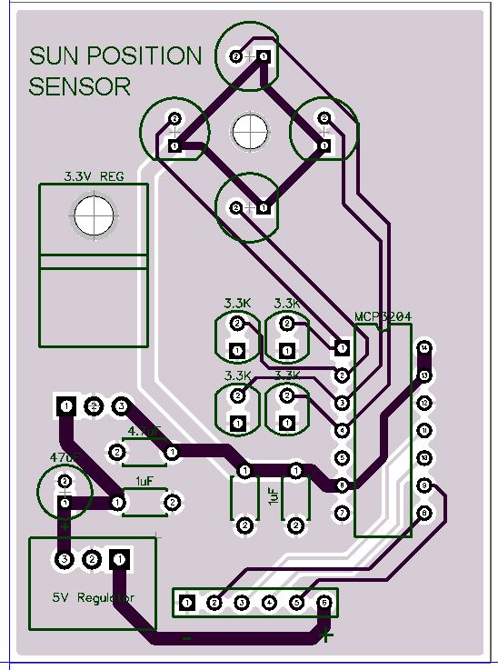
548 x 737 - 227K
Comments
Since the bulk of this project is on the Propeller 1 forum I can't see why you are posting here as these "sensors" are just part of that project and if anyone has been helping you then you are kinda stuffing them about.
However if you are going to run 5' why don't you design in a 10-way IDC rather than a 6 way pin header. That way every odd wire can be a ground which will help shield the signals and IDC cables are very easy to make up. You say you are using CAT5 but you have made absolutely no allowance for this on the pcb, If some wires are grounds then they need a pad for each but surely you would just design in an RJ45 socket???
You don't really need the 5V switching regulator as your current drain would be so very low so it doesn't matter if you run 12V into the 3.3V reg as long it is spec'd for that voltage of course. The MCP3204 will only be drawing less than 1ma so the power dissipation will be minute at around 12V - 3.3V * 1ma = 8.7mW it won't even start to warm up. BTW, that reg is a clunker, why don't you use some smaller ones, even TO92 if you are using TH parts. So in general having smaller regs you can position them much closer to the chip where they are needed.
You must learn to put your decoupling caps right next to the supply pin of the chip which is pin 14 to be really effective. Although you can tie Vref directly to the supply it won't hurt to use an RC filter for this pin, say 100R + 10uF to keep it stable. Just use pullups on the signal lines, for these longer distances use smaller values like 2K2 or thereabouts.
For the ADC I would have just programmed a little $1 PIC chip to autoscan the sensors and spit it out serially so that it would only need a single signal wire and one I/O on the Prop. Don't dismiss this option, it's a lot easier than you may think and pays off on other projects too. Besides these cheap little PICs/AVRs/8051s etc have their own voltage references built-in as well as temperature sensors etc. The MCP320x chips, while handy, just seem clunky when compared to a more powerful and cheaper option.
The box that houses this board is a modified halogen lamp case which I had to dremel and glue in the RJ45 connector at the bottom then extend out the pins to solder to the board. The position of the jack is necessary.
The reason for the larger components is because I am not familiar with many components except ones that I have already bought and used in other projects. I suppose trying to find an alternative one could be handy to use for smaller circuits.
I am also not familiar with PIC chips and since I am still learning about ADC's, I figured I would try this on this sensor. The sensor board can always be changed in the future for a small cost.
As for grounding left over wires in the CAT5 cable.... Would that ground be connected between both boards or just one? If just one, which one? Sending "data" over distances has always been an issue for me which is what I am trying to learn about now.
Some of the stuff I say is more general, for next time perhaps.
The ground wires are just like the power ground, connected both ends (of course). CAT5 twisted pair only has four pairs but the IDC cable can easily have a ground with every signal. Sending data over a few feet is not a problem except maybe if you have high-speed signals and/or a noisy environment. That's kinda why I mentioned having a PIC just spit data down the line at a reasonable rate whereas the MCP3204 runs at SPI speeds and you have to ask for a lot of samples to get an average whereas the PIC/micro can average it all up and send it at a much more leisurely rate. Sometimes instead of a cheap micro it is just as easy to use another Prop although the PIC type approach can mean something as simple as an 8-pin DIP.
Remember to protect the Prop I/O over these long lines by incorporating series resistors in the I/O, you can easily make the inputs to the Prop 10K and the outputs 220R or more, especially for signals. Ideally the pullups will be on the Prop side, not the remote end.
It doesn't cost you anything to make the pcb connector an RJ45 or an IDC style, even if you solder from there to an RJ45 because of the current box you have.
Most commonly, the ribbon cable has every other wire attached to ground to create shielding. This is what floppy drives and hard drives did for ages until the new SATA interface achieved superior feed.
For a mere 5 feet, it certainly might be an easier build than CAT5 cable, and maybe a bit cleaner.
And if you really have a remaining problem, there are ribbon cables that actually are not just flat, they have a twisted pair so that each signal is mated with a ground. So you have a plan B if a plain old ribbon cable still has a noise problem. 3M makes the twisted stuff.
http://en.wikipedia.org/wiki/Insulation-displacement_connector
http://uk.rs-online.com/web/c/cables-wires/ribbon-flat-cable/twisted-ribbon-cable/
I am already up to $100 for PCB boards and new components I don't already have on hand. I was trying to stay as close to $100 as possible but with having to change to new parts that could replace something I have on hand, it keeps adding to the cost.
Right now, I have :
Pin 8 : Ground
Pin 7 : N/A
Pin 6 : MISO
Pin 5 : CLK
Pin 4 : MOSI
Pin 3 : CS
Pin 2 : N/A
Pin 1 : 12V+
Should I rearrange these in any specific order and ground the N/A pins?
1) Primarily discussed is noise created on the CAT5 signal lines to or from the ADC.
2) Very little mention is made of the noise on the ADC board that may cause inaccurate measurements.
1) Signal line noise is likely ringing (reflections) due to impedance mismatches. To get a clean clock and dataIn at the far end you would match your source impedance with your line impedance (No termination ). The prop output probably has a low output impedance of about 82 ohms (3.3 / 40ma) ?? The CAT5 probably has a characteristic impedance of about 110 ohms. If you add 40 to 50 ohms in series you'll get a nice clean clock at the ADC input.
Now data coming out of the of the ADC might be able to do the same-- put a 40 to 50ohm resistor in series, a 2k pull up on the main board (if the ADC is open drain) then Jacks 10k series resistor in series. You'd never want to put the pull-up on the prop input side or you'd create a voltage divider +3.3 2K -> 10k -> low drive (Yikes).
Getting clean signals to / from the ADC should be pretty easy, even at a 2MHz clock rate.
Clock and Data should be twisted with ground and power (yes I said power, it's AC impedance not DC). That is clock & dataIn twist with their own grounds and dataout twists with power; it's the same thing that's done on 4 layer PCBs with power and ground planes. Idd is so small there shouldn't be much drop therefore two wires, one for power and two for ground, will be more than adequate. CS does not need anything special, just a 2k pull-up on the prop output and a 5k in series. The CS transition will be so slow there will be no ringing at all. In fact it might be too slow, but what else can be done for "protection".
What is the prop being protected against exactly? ESD, lightning strikes?
2) The ADC is important too. How much noise is acceptable to get the job done? How accurate does it need to be? What is the sensor range of voltage that will be measured?
If your 3.3K resistors are 1% instead of 0.1% you may find variations from part to part will throw off accuracy. Using the 3.3V as a VREF / 4096 (which is also your PS) your LSB resolution will be about 800uV. The resistor +/- 1% variation is 66mv (1% of 3.3V X 2). An 8 bit converter is 1/256 = 0.4 % or 13mV. The same considerations should be given to your photo detectors and V reference. If the VDD (3.3V) varies 1% it will also throw off the ADC voltage readings.
Maybe accuracy isn't that important and all you really need is something that's kinda in the ballpark. Well if one sensor reads high and the other low then what you get back to the prop might be the exact opposite of what you need. So you'd send the positioner in the wrong direction. Okay, so calibration might be in order. In the field accessibility might matter too. Is there a way to automate calibration?
AC Noise:
The small area of the sensors, pull-downs, and inputs to the ADC is where AC noise can get in. Once ADC readings are digitized your guard-band jumps up to 1.5V. From that point on the readings, which are now in digital format, are very resilient.
If you haven't already, you might want to breadboard the photo-detectors and resistors and use a precision DVM to measure all four nodes. Or you might want to use 1 resistor and characterize all the photo-detectors you have and cherry pick the ones closest to each other. Good Luck.
Pin 8 : CLK
Pin 7 : Ground
Pin 6 : MOSI
Pin 3 : Ground
Pin 5 : Spare with extra pads
Pin 4 : CS
Pin 2 : MISO
Pin 1 : 12V+
You don't want an active signal paired with an active signal. 2, 4, 6, 8 are signals the odds are DC/ground.
That is a bunch of information to soak in! I will have to read this when I get home from work and go line by line and make the changes. Hopefully I understand it
Ummm. RS485/422 is Asynchronous serial.
The project is synchronous serial in the form of SPI. So RS485/422 would require a conversion.
So hoping I understand.... The 50 ohm resistor would go on the sensor board and then on the main board, I would put a 2.2K pull up to 3.3V then a 10K series resistor to the Prop pin? I cannot put the pull up resistor on the sensor board?
Looking at your latest layout I should have been clearer.
Main board 50 ohm in series = CLK, dataIn, CS
Sensor 50 ohm in series = dataOut.
2-3K pull ups connected to the output pins.
The impedance is guess work and somewhat based on the prop specs. So I'm going to measure it with a length of coax and get back to you with a real number for the prop. This will give you the correct number for the series resistor to back terminate.
Also... can I use, or is it advisable to use the pull up trace connection to the 3.3V of the the Prop or should I route it elsewhere? If I need to route it elsewhere, I will probably have to do a jumper wire.
Of course differential drivers can used for synchronous protocol like SPI as well.
You may be right, but I have never seen RS485/422 drivers actually used to create a long wire SPI interface.
There are alternatives where distances increase.
Dallas Systems has a 1-Wire ADC product http://www.maximintegrated.com/en/products/comms/one-wire/DS2450.html
And one can always use the MCP2551 and MCP2551 chip set to create a CANbus node with a small microprocessor that has ADC on board.
Why bother with 3 twisted pairs or more and the RS485/422 chips?
No reason you cannot use RS485/422 driver chips and twisted pairs of a cat5 cable for the clock and data signals used by SPI or I2C.
See how simple the circuit can be, and you only need a 3 or 4 core and a single I/O on your Prop.
I can program a couple of these 8-pin DIPs up today and drop them in the post gratis. They scan 4 inputs and average and output the values serially, all you have to do is read the 9600 baud stream coming in:
<00> <sensor 1> <sensor2> <sensor3> <sensor4> <CR>
or something like that.
@Loopy: there are more things you haven't seen than you have seen. Using RS485 drivers for something other than RS485 is normal, just as I use RS232 drivers to differentially drive piezo transducers.
Yes.. this thread has begun to wander off into the weeds.
Domanik seems to be sincerely trying to address the electrical noise issues of what the OP is trying to do.
completely agree.
And since I am more used to AVRs I would use a ATtiny13 (8-PIN DIP) with this little BASCOM Basic code
basically same schematic.
$regfile = "attiny13.dat" $crystal = 9600000 Config Portb.0 = Output Open "COMB.0:9600,8,N,2" For Output As #1 Config Adc = Single , Prescaler = Auto , Reference = Avcc 'Now give power to the chip Start Adc Dim W As Word , channel As Byte 'now read A/D value from channel 0 .. 3 Do Print #1 , "!" For channel = 0 To 3 W = 0 For Cnt = 0 To 63 W = W + Getadc(channel) Next Cnt Print #1 , W ; " " ; Next channel Print #1 Loop EndThe values I used for both of the Shunt resistors was 330 Ohms, and the Series resistance was that of the wire ... 10 feet of #22 wire has a resistance of about 0.161 Ohms.
Reference:
http://chemandy.com/calculators/matching-pi-attenuator-calculator.htm
http://www.cirris.com/learning-center/calculators/133-wire-resistance-calculator-table
1) SPI is push-pull and therefore does not require pull up resistors. Adding pull-up resistors to SPI is a bad idea. I2C is predominately open drain and therefore requires pull-up resistors.
2) I think a reasonable method of determining output impedance is with the formula Vol/Iol. I can't find these specs for the Propeller so my guess is the prop can put out 40ma and achieve a V out minimum of 400mv. This yields a source impedance of 10 ohms (not 82 as I previously guessed, sorry). It should be the same for a high drive. All of this is good news for improving signal fidelity and speed.
3) Furthermore, the SPI does not have IO pins which simplifies the series resistor requirements.
I've simulated a CAT5 transmission line and inserted a 1 ohm, 200 ohm and 100 ohm resistor (R1). Large resistor values above 500 ohms tend to slow the RT/FT significantly. The round trip delay is about 18ns, so the time from a CLK going high to dataO coming back is increased by that much versus the ADC being on the main board, which is minor.
The transmission line is made up of 3 series 3ns 120ohm lines together with distributed 4pf parasitic capacitance. The CAT5 ground return is through a 20mil/24ga solid wire with a resistance of 0.128 ohms which is distributed along the ground return. In each simulation run only R1 is changed, from 1 ohm to 200 ohms then to 100ohms.
In SPI-IMP-1 there is significant ringing at the ADC input and voltage ringing on V(Igr1) which is the ground return to the main board as measured at the ADC. The I(R4) and I(R1) demonstrate ringing current in the cable which can induce some noise, although insignificant.
In SPI-IMP-200 the 200 ohm resistor slows down RT/FT thereby reducing overall noise. The RT is about 50% of max spec for the MCP3204.
In SPI-IMP-100 the 100 ohm resistor is a good compromise for best RT (~20n) and quiet ground with 8ma peak current. The plots have been expanded for a more detailed look. The ground offset of 400uV won't affect the ADC when it's taking a sample during the clock transition. On the ADC analog input there should not be noise induced because of signal transitions.
--Attachment not found.
--Attachment not found.
--Attachment not found.
A couple of side notes:
If the main board supplies +12V, 40ma current to run the ADC it will cause a 5mv DC offset in the ground between the two boards. Not a concern.
It's likely that DC Power/ground offsets can be eliminated by using an isolated switching regulator on the ADC board.
The specs on the MCP3204 have 400mv Vol at 1ma which gives us a source impedance of 400 ohms. No series resistor needed on dataOut if these are truly indicative of typical values.
The bottom line is the SPI can run much faster than the I2C while operating over longer CAT5 cable lengths.
I tend to lump all the little 8-bit micros in under the "PIC" banner
As for how best to handle "high-speed" signals over cable lengths in noisy environments I would treat that as a more advanced exercise or as forum tutorial perhaps. In the meantime get the job done properly (as in don't make it so complicated). The serial output of the little micro will be fairly noise immune as there are no high-speed signals, a lazy 9600 baud even with 10 character timing will still give an update rate of close to 100 times per second. The output of the serial is low impedance anyway and those little glitches that might break through aren't much of a nuisance when the bit timing is around 100us vs SPI timing.
As I said Tim, using little micros such as these is really useful, see how simple the code and hardware becomes! It's a bit like a 3D printer, you make up the part you need, quick and easy, in this case roll your own custom ADC. There is plenty of support for PICs and AVRs, even 8051s and MSP430s etc. Just pick a cheap eval kit and you will never look back.
BTW, besides saving on the cost of MCP3204s and noise suppression etc you can also save on the power supply. Since the micro only needs milliamps you can even run a simple shunt regulator from 12V with a resistor and for a zener I would just use 2 red LEDs in series for my 3.3V supply. Add a 10uF tantalum and 100nF and Bob's your uncle. Let's see micro+PSU will end up costing around a buck or two, but probably less than the MCP3204 alone.
See how simple the circuit can be, and you only need a 3 or 4 core and a single I/O on your Prop.
No arguments from me on that point, far simpler to use a uC with built in ADC's and let it take some of the computational load as well, but there are times when you either have to work with the parts you have, the parts that are already there, or the parts the customer specifies. If the the problem is corrupted serial data then more a robust data transmission method may be the way to go under some circumstances. My suggestion was made to enable the op to work with the parts he listed.