Shop OBEX P1 Docs P2 Docs Learn Events
Overshoot / ringing on TTL serial signal - OK or not? — Parallax Forums

Overshoot / ringing on TTL serial signal - OK or not?

pmrobertpmrobert Posts: 673
edited 2014-11-16 10:33 in Propeller 1
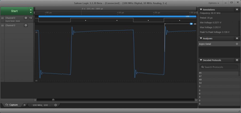
Attached is a scope cap showing some overshoot/ringing at transitions. Is this the Gibbs Phenomenon my searches have led me to? Should I be concerned? Would a pullup or pulldown damp this out? The scope and C3 board have a shared, single point ground and the scope probe wire is only about 6" long. The purpose of this serial link is for comms between two C3 boards; the scope captures show no difference whether the two are connected or not.
TIA, Mike

Edit: added zoomed analog trace.
1024 x 289 - 37K
1024 x 481 - 40K

Comments

  • Peter JakackiPeter Jakacki Posts: 10,193
    edited 2014-11-14 18:45
    pmrobert wrote: »
    Attached is a scope cap showing some overshoot/ringing at transitions. Is this the Gibbs Phenomenon my searches have led me to? Should I be concerned? Would a pullup or pulldown damp this out? The scope and C3 board have a shared, single point ground and the scope probe wire is only about 6" long. The purpose of this serial link is for comms between two C3 boards; the scope captures show no difference whether the two are connected or not.
    TIA, Mike

    Edit: added zoomed analog trace.

    The signals are slow and the ringing is minimal and could be from the probe, you didn't say whether it was x1 or x10 and whether they had been compensated (trim capacitor in probe). Even if this is exactly what's there none of this will cause any problems especially at the slow speed you are running at.
  • pmrobertpmrobert Posts: 673
    edited 2014-11-14 18:57
    I obtain the same trace with a properly trimmed Tek analog CRT scope (I should have mentioned that) so I don't think it's the probe. I have run this link at 500K, any faster than that framing errors creep into the picture. This is under GCC using fdserial. The highest reliable speed is my goal, perhaps I should look at SPI?
  • Peter JakackiPeter Jakacki Posts: 10,193
    edited 2014-11-14 19:04
    pmrobert wrote: »
    I obtain the same trace with a properly trimmed Tek analog CRT scope (I should have mentioned that) so I don't think it's the probe. I have run this link at 500K, any faster than that framing errors creep into the picture. This is under GCC using fdserial. The highest reliable speed is my goal, perhaps I should look at SPI?

    Anything full-duplex in one cog cannot time accurately at higher baud rates. Use one cog for receive and one for transmit and then you can easily go into the megabaud region. The framing errors are simply from the one cog dividing it's time between two tasks and the critical one is receiving.

    But you do know what I mean about the probe though, don't you? (hook it onto the probe comp signal on the scope and trim the probe's cap for a clean square wave).
  • LawsonLawson Posts: 870
    edited 2014-11-14 19:09
    That ringing looks fine, and could easily be the long 6" ground wire on the scope probe. If you really want to see the shape of that edge, disassemble the tip of the scope probe till you have a point sticking out of an exposed shield. Next find/make a spot where the point can touch your signal, while the shield touches the nearest ground. With a <3/4" ground loop the probe ringing should be gone.

    Marty
  • pmrobertpmrobert Posts: 673
    edited 2014-11-14 19:29
    Peter, yes, I'm aware of the importance of trimming the probe, thanks for mentioning that. The old Tek2213 scope's probes are trimmed properly using the scope's 1kHz reference signal. What started my quest for knowledge here is the 500Kbps signal - it decodes properly on both the LA and the intended receiving Prop but blows up faster than that, see attached LA screen cap. Though I use fdserial, the rx on the master processor is only used in a half duplex manner, it only receives a 2 byte checksum from the target processor after each transmitted packet to determine whether to retransmit or not. Marty, excellent idea, I'll give it a shot and see if that exorcises my probably imaginary gremlins. I think Peter's right on with the timing becoming jittery due to that cog checking for rx whether or not there's anything there or not. One thing I do have with this project is a veritable plethora of spare pins. I'm almost considering an 8 bit parallel transmission scheme....
    1024 x 481 - 56K
  • Peter JakackiPeter Jakacki Posts: 10,193
    edited 2014-11-14 20:34
    pmrobert wrote: »
    Peter, yes, I'm aware of the importance of trimming the probe, thanks for mentioning that. The old Tek2213 scope's probes are trimmed properly using the scope's 1kHz reference signal. What started my quest for knowledge here is the 500Kbps signal - it decodes properly on both the LA and the intended receiving Prop but blows up faster than that, see attached LA screen cap. Though I use fdserial, the rx on the master processor is only used in a half duplex manner, it only receives a 2 byte checksum from the target processor after each transmitted packet to determine whether to retransmit or not. Marty, excellent idea, I'll give it a shot and see if that exorcises my probably imaginary gremlins. I think Peter's right on with the timing becoming jittery due to that cog checking for rx whether or not there's anything there or not. One thing I do have with this project is a veritable plethora of spare pins. I'm almost considering an 8 bit parallel transmission scheme....

    Well I do have a 3M baud object that I have been meaning to tidy up for the OBEX but there's also another one already in the obex mentioned here. Comparing the two I can see mine will run faster as it is designed to operate at 100% throughput at 2M baud by partly buffering before the single stop bit that may only exist before the next character. My object also rejects false start bits and detects breaks and also rejects floating receive lines. No need to go parallel.

    I still suspect the probe in your shots there because I see a droop after the ringing which doesn't look right and I didn't quite catch that you had a 6" ground lead, whoa! But still these are slow speed signals and there is nothing to be worried about.
  • Timothy D. SwieterTimothy D. Swieter Posts: 1,613
    edited 2014-11-15 19:41
    Slight off topic, but pmrobert, it looks like you are using the latest Saleae hardware (judging from your screenshots). How do you like it?
  • edited 2014-11-16 10:33
    pmrobert wrote: »
    Attached is a scope cap showing some overshoot/ringing at transitions. Is this the Gibbs Phenomenon my searches have led me to? Should I be concerned? Would a pullup or pulldown damp this out? The scope and C3 board have a shared, single point ground and the scope probe wire is only about 6" long. The purpose of this serial link is for comms between two C3 boards; the scope captures show no difference whether the two are connected or not.
    TIA, Mike

    Edit: added zoomed analog trace.

    Isn't that normal 'ringing'? After the fist rise of the start bit you would normally wait 1.5 bit periods before sensing the first data bit and 1 bit period thereafter. That avoids the area at the tranition where that little bit of ringing occurs.

    For coding purposes it might easier to wait one half bit period, sense 10 bits and then mask off the start and stop bits.

    As Shultz used to say on the old Hogan's Heros series. "i know nothing. Nothing!"

    Sandy
Sign In or Register to comment.