

Reduce power / resistors + replace clip-battery homework board
 fuichris
Posts: 26
fuichris
Posts: 26
Hi all,
I've done the Advanced Search and Support FAQ and still uncertain, hope to get your help.
(Q #1) HOW TO REDUCE THE VOLTAGE?
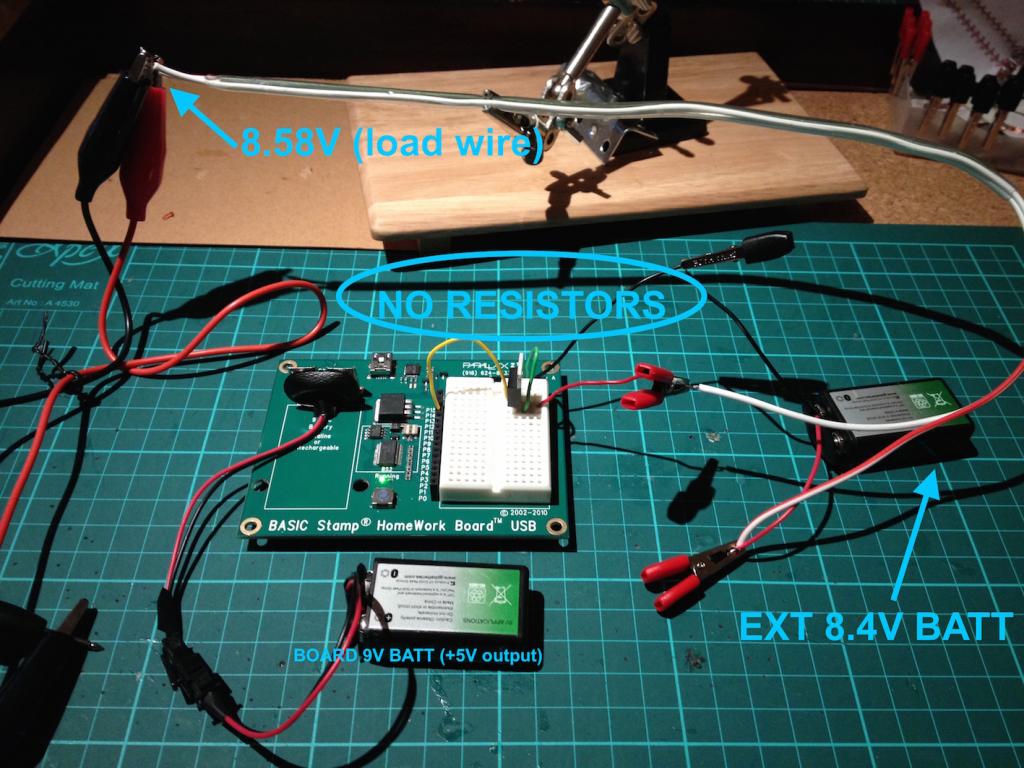
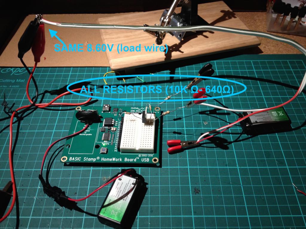
I'm trying to figure out why the voltage of my load (in this photos below, just +- wires attached to my multimeter), doesn't go down when I use resistors? My project is just an on/off with the MOSFET and involves simply putting heat to the flexinol muscle wire (see drawing), so I need to reduce the voltage because it keeps burning the wire out. See all the visual explanations... I'm a newbie ;p
Please see below:
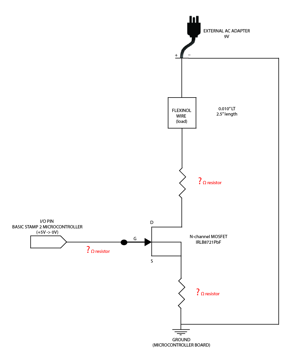
- circuit diagram (hopefullly correct)
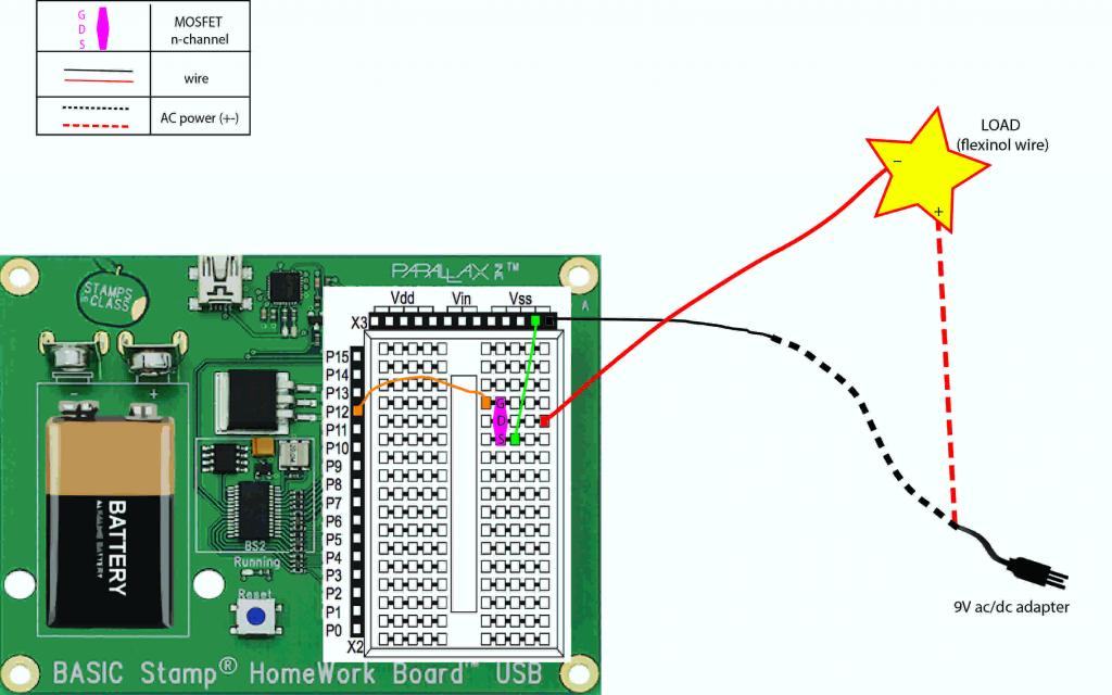
- illustrated set-up
- photo of setup


DETAILS:
- MOSFET N-channel (IRLB8721PbF)
- BS2 Homework Board (9V clip batt)
- External Battery = 9V ac/dc adapter to wall
(Q#2) REPLACE BOARD BATTERY
I wanted to remove the 9V battery clipped to the homework board that activates the microcontroller because the project needs to run indefinitely. The External Battery will already be a AC to a wall, so I can't use another AC to the wall for the microcontroller. Any advice?
HELLLLPPPPPP ! Thanks folks!
I've done the Advanced Search and Support FAQ and still uncertain, hope to get your help.
(Q #1) HOW TO REDUCE THE VOLTAGE?
I'm trying to figure out why the voltage of my load (in this photos below, just +- wires attached to my multimeter), doesn't go down when I use resistors? My project is just an on/off with the MOSFET and involves simply putting heat to the flexinol muscle wire (see drawing), so I need to reduce the voltage because it keeps burning the wire out. See all the visual explanations... I'm a newbie ;p
Please see below:
- circuit diagram (hopefullly correct)
- illustrated set-up
- photo of setup
DETAILS:
- MOSFET N-channel (IRLB8721PbF)
- BS2 Homework Board (9V clip batt)
- External Battery = 9V ac/dc adapter to wall
(Q#2) REPLACE BOARD BATTERY
I wanted to remove the 9V battery clipped to the homework board that activates the microcontroller because the project needs to run indefinitely. The External Battery will already be a AC to a wall, so I can't use another AC to the wall for the microcontroller. Any advice?
HELLLLPPPPPP ! Thanks folks!

1024 x 1225 - 642K

1024 x 768 - 128K
1024 x 768 - 130K
1024 x 640 - 81K
Comments
The resistor should go in the MOSFET Drain Lead. You want the MOSFET Source lead directly to negative in most cases.
To guess at the resistor value, use an ohm-meter to measure the muscle-wire resistance and put in a resistor about the same size to start. That will give you about 1/2 the voltage. The current will be quite high, so the resistor will need to have the proper wattage rating.
If you happen to know the muscle-wire ratings as to voltage and current, its a simple calculation with Ohm's Law to get a suitable resistor.
Cheers,
Ahh - I looked again at your pictures and you've done this. Why not just use the same power source as you're using for the muscle wire? The HomeWork Board, like other Stamp Boards, can operate with a power supply ranging from 6V to 24V or higher. You have to pay close attention to the voltage regulator's power dissipation if you have more than 12V available, but your project doesn't use much current.