Trouble using I2C
Hi everyone.
I just got the propeller and I am hoping to use it as part of a project for control of a Quad-rotor. At the moment trying to write to and read to my 9DOF sensor stick (https://www.sparkfun.com/products/10724). I have tested the 9DOF with a different micro and it works. This leads me to believe that I am miss some basic command, such as a stop command at the end of each communication. I believe this is the problem as each time I add code or write to a new register/chip on the 9DOF it effects what I am writing to the register in my code. Any help would be greatly appreciated. See current code below and pictures of my current circuit. (note VDD and GND are only connected in some pics as the blue LED on the PCB is quite bright)
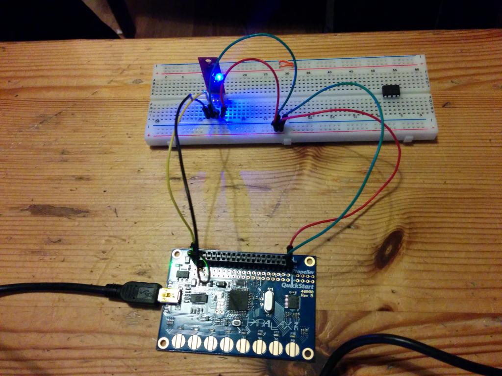
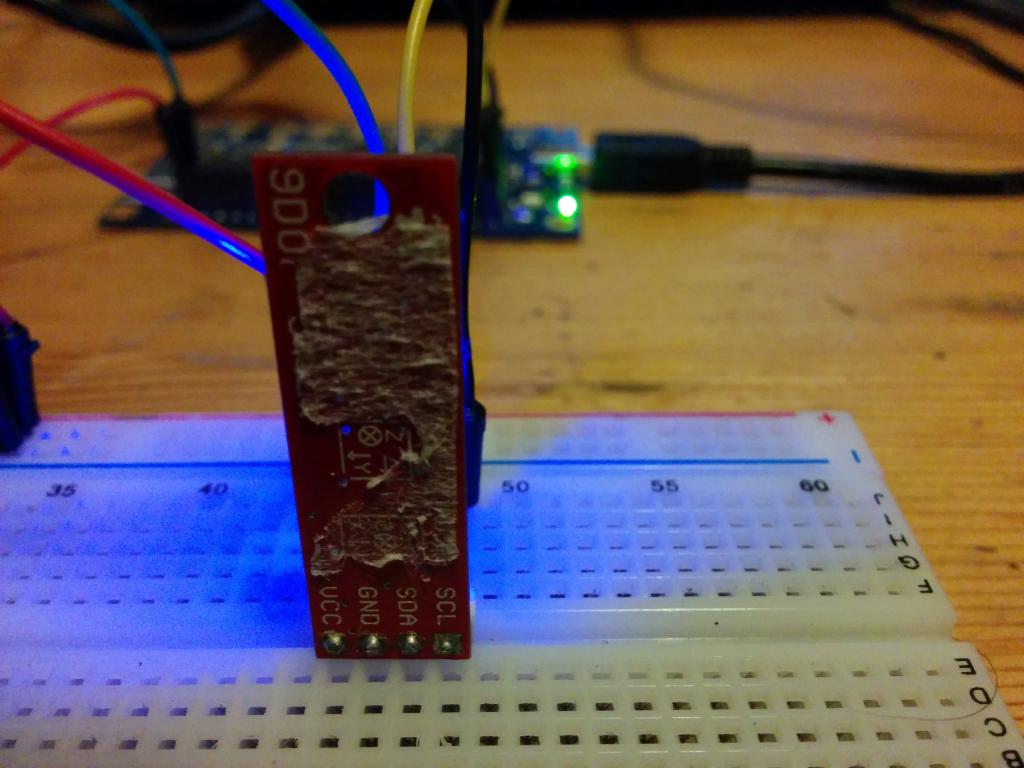
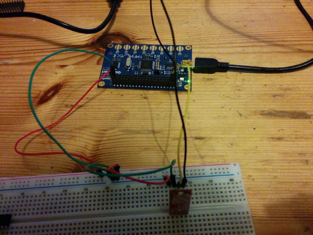
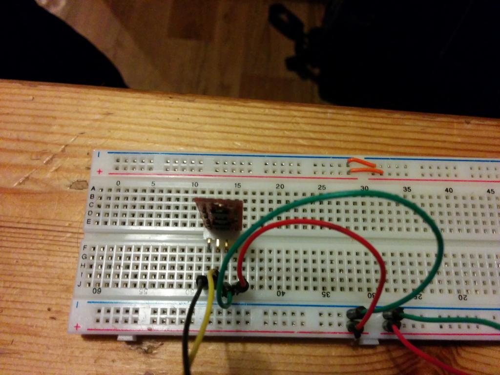
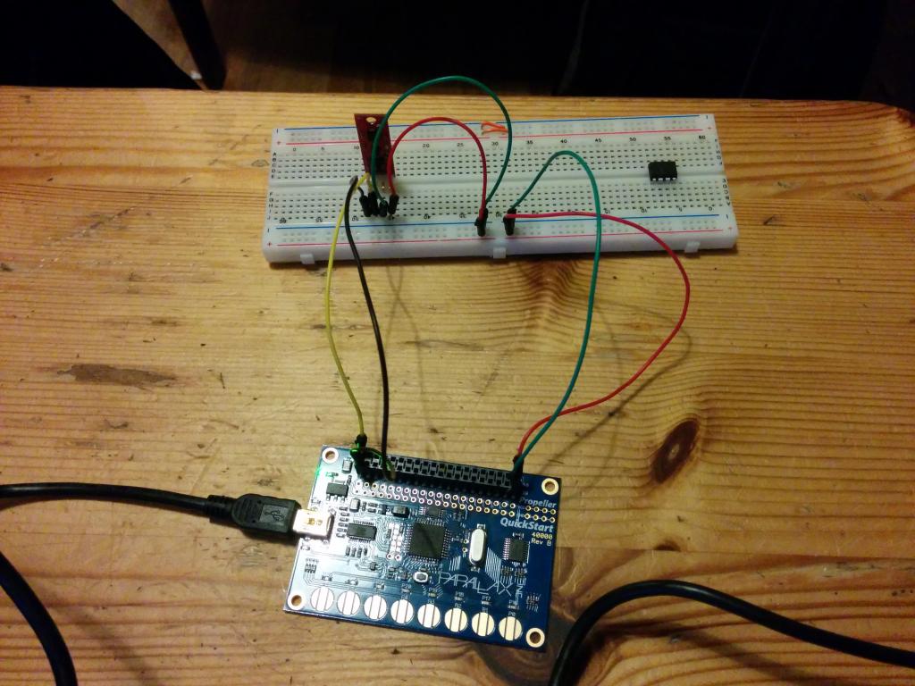
I just got the propeller and I am hoping to use it as part of a project for control of a Quad-rotor. At the moment trying to write to and read to my 9DOF sensor stick (https://www.sparkfun.com/products/10724). I have tested the 9DOF with a different micro and it works. This leads me to believe that I am miss some basic command, such as a stop command at the end of each communication. I believe this is the problem as each time I add code or write to a new register/chip on the 9DOF it effects what I am writing to the register in my code. Any help would be greatly appreciated. See current code below and pictures of my current circuit. (note VDD and GND are only connected in some pics as the blue LED on the PCB is quite bright)
//https://propsideworkspace.googlecode.com/hg/Learn/Simple%20Libraries/Protocol/libsimplei2c/html/simplei2c_8h.html#a65bcbd826cf4a1dc5cf475cfd48b5526
//See above for commands
#include "simpletools.h"                      // Include simple tools

i2c *Nine_DOF_Bus;

const int DofSCL = 0;
const int DofSDA = 1;

const int accAddr   = 0b1010011;                     //Ox53 (followed by read or write)corrosponding to OxA6 for write and OxA7 for read
const int magnAddr  = 0b0011110;                     //Ox1E (followed by read or write)corrosponding to Ox3C for write and Ox3D for read
const int gyrosAddr = 0b1101000;                     //Ox68 (followed by read or write)corrosponding to OxD0 for write and OxD1 for read


void Acc_setup(int Bus_ID, int Device_Addr)
{

   unsigned char Read_back[] = {0,0} ;
   i2c_in(Bus_ID , Device_Addr , 0x00 ,1 , (unsigned char*)Read_back ,2);   //Code to test the device ID. It should be 0xE5 or 0b11100101
   print("Accel ID is: %x \n",Read_back [0]);                            //Should Read back 0xE5 (But reads back 0, Cleary I am doing some thing stupid :(. )

   i2c_out(Bus_ID, Device_Addr, 0x2D ,1 , 0x00 ,2);                       // Write to Reg 0x2D so as to change the part from standy (0x00) to (0x08) measure mode.
   i2c_out(Bus_ID, Device_Addr, 0x2D ,1 , 8 ,2);                       // Write to Reg 0x2D so as to change the part from standy (0x00) to (0x08) measure mode.
   i2c_in(Bus_ID , Device_Addr, 0x2D ,1 , (unsigned char*)Read_back ,2);   // Print to serial to see if 0x08 was to reg 0x2D (REMOVE LATER)
   print("Read from reg 2d: %x \n", Read_back[0]);


    i2c_out(Bus_ID, Device_Addr, 0x38 ,1 , 0x84 ,2);                      //Write to Reg 0x38 so as to chage FIFO to 'stream' and sets D2 to 1
    i2c_in(Bus_ID, Device_Addr, 0x38 ,1 , (unsigned char*)Read_back ,2);  // Print to serial to see if 0x84 was to reg 0x38 (REMOVE LATER)
    print("Read from reg 38: %x \n",Read_back[0]);

}

void Mag_setup(int Bus_ID, int Device_Addr)
{
   unsigned char Read_back[] ={0x00 ,0x00};
   i2c_in(Bus_ID , Device_Addr , 10 ,1 , (unsigned char*)Read_back ,2);   //Code to test the device ID. It should be 0x48
   print("Mag ID is: %x \n",Read_back [0]);                               //Print to see if the regsistor is write was 0x48.


   i2c_out(Bus_ID, Device_Addr, 0x00 ,1 , 0x70 ,2);                      //Write to Reg 0x00 so as to set the number of averaging to 8 samples per measurement output and also to change the Data Output Rata to 15 Hz
   i2c_in(Bus_ID , Device_Addr , 0x00 ,1 , (unsigned char*)Read_back ,2);
   print("Reg 0x00 is: %x \n",Read_back [0]);

  i2c_out(Bus_ID, Device_Addr, 0x01 ,1 , 0xA0 ,2);                      //write to Reg 0x01 so as to set gain of the device
  i2c_in(Bus_ID , Device_Addr , 0x01 ,1 , (unsigned char*)Read_back ,2);
  print("Reg 0x01 is: %x \n",Read_back [0]);

  i2c_out(Bus_ID, Device_Addr, 0x02 ,1 , 0x00 ,2);                      //write to Reg 0x02 so as to set the mode to continues-measurement mode
  i2c_in(Bus_ID , Device_Addr , 0x01 ,1 , (unsigned char*)Read_back ,2);
   print("Reg 0x02 is: %x \n",Read_back [0]);

}


int main()                                    // Main function
{

Nine_DOF_Bus = i2c_newbus(DofSCL, DofSDA, 1);  // Setup the Nine_DOF_I2C_Bus

Acc_setup(Nine_DOF_Bus, accAddr);
Mag_setup(Nine_DOF_Bus, magnAddr);


  while(1)
{
  }

  return 0;
}


Comments
unsigned char regs[] = {0x00, 0x08}; i2c_out(Bus_ID, Device_Addr, 0x2D, 1, ®s[0], 1); // Write to Reg 0x2D so as to change the part from standy (0x00) to (0x08) measure mode. i2c_out(Bus_ID, Device_Addr, 0x2D, 1, ®s[1], 1); // Write to Reg 0x2D so as to change the part from standy (0x00) to (0x08) measure mode. // or unsigned char regs[] = {0x00, 0x08}; i2c_out(Bus_ID, Device_Addr, 0x2D, 1, regs, 2); // Write to Reg 0x2D so as to change the part from standy (0x00) to (0x08) measure mode.I'm not entirely sure whether the second version works as such. It may well be that the register address keeps getting incremented. That would require source inspection. Writing each byte separately (long version) should definitely work.Why do you need the write 0x00 as well? I'd assume that the register is already 0 and you only need the change to 0x08.
The code that I have written is as below.
#include "simpletools.h" // Include simple tools
#include "simplei2c.h"
i2c* ADCSBus; // I2C bus ID
const int SDA=4; // Chip SDA pin
const int SCL=3; // Chip SCL pin
// Registry and Command values
const int GyroAddr = 0x68; //0b1101000
const int accAddr = 0x53; //0b101001153
const int magnAddr = 0x1E; //0b0011110
const char accread =0xA7;
const char accwrite =0xA6;
const char TH = 0x1B; // Register value for TEMP_OUT_H
const char ZH = 0x21; // Register value for GYRO_ZOUT_H
const char ZL = 0x22; // Register value for GYRO_ZOUT_L
void Acc_setup(int ADCSbus, int Device_Addr)
{
unsigned char Read_back[]={0,0};
i2c_in(ADCSBus, Device_Addr,0x00,1,&Read_back,2);
print("Accel ID is: %x \n",Read_back[0]); //should be 0xE5
unsigned char regs[] = {0x00, 0x08};
i2c_out(ADCSbus,Device_Addr,0x2D,1,®s[0],2); //change from standby to measure mode
i2c_out(ADCSbus,Device_Addr,0x2D,1,®s[1],2); //write 0x2D
i2c_in(ADCSbus,Device_Addr,0x2D,1,&Read_back,2);
print("Read from reg 2d: %x \n",Read_back[0]); //to check if ox08 is written onto reg 0x2D
unsigned char reg2[] ={0x84};
i2c_out(ADCSbus,Device_Addr,0x38,1,®2[0],2); //change FIFO to stream and set D2 to 1
i2c_in(ADCSbus,Device_Addr,0x38,1,&Read_back,2); //0x84 should be written to reg 0x38
print("Read from reg 38: %x \n",Read_back[0]);
}
int main() // Main function
{
i2c *ADCSbus = i2c_newbus(SCL, SDA, 0);
Acc_setup(ADCSbus,accAddr);
while(1)
{
uint16_t x16,y16,z16; //16 bit variables
uint8_t data[6];
int datReg =0x32;
i2c_in(ADCSBus, accread >> 1 , datReg, 1, data, 6); // ******************************
x16 = (data[0] << 8) | data[1];
y16 = (data[2] << 8) | data[3];
z16 = (data[4] << 8) | data[5];
print("%cx=%d, y=%d, z=%d%c\n",HOME, x16, y16, z16, CLREOL);
}
}