Shop OBEX P1 Docs P2 Docs Learn Events
C3 board repair possible? — Parallax Forums

C3 board repair possible?

pmrobertpmrobert Posts: 677
edited 2014-10-21 07:57 in Propeller 1
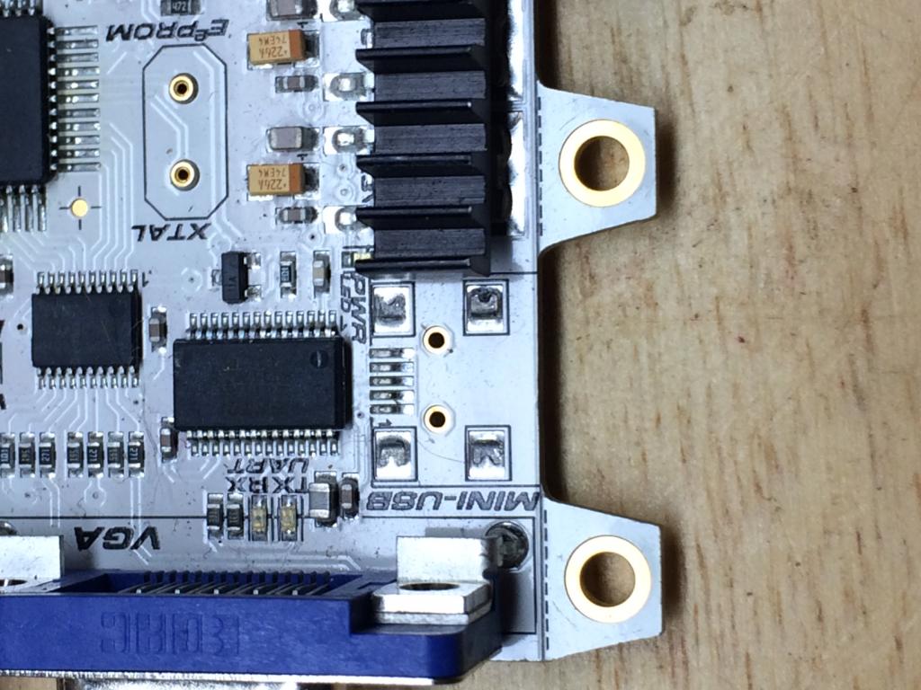
I made a huge mistake by not unplugging the USB cable from my C3 board prior to packing it in a backpack. The mini-USB connector was pried/pulled off the board and I am wondering if anyone has the nerves, eyes and equipment to replace that connector. Please see attached image; I think it's fixable as the board itself does not appear to be damaged and the traces were not pulled up as far as I can tell. I will be more than happy to pay a fair price for this repair. Can anyone help me?

Thanks, Mike R.....
1024 x 768 - 117K

Comments

  • doggiedocdoggiedoc Posts: 2,245
    edited 2014-10-12 17:50
    Mike,

    My knee-jerk reply is that it can be done. However, I'll need to dig out my C3 to evaluate it more closely. The clearances for the other components could pose some difficulty.

    I'll look.

    Doc
  • PropGuy2PropGuy2 Posts: 360
    edited 2014-10-12 17:58
    Yes - it can be done. I did the same thing to a Prop Proto board and it worked afterwards. You are lucky that the traces were not damaged, most likely because the solder is very soft and broke cleanly. To be successful you need the board and USB connector to be very clean. Use the sharpest tip soldering iron tip you can find (needle point) and brand new out of the box. Use new solder paste and evenly coat the PCB pads and USB connector tabs with the solder paste. Put the smallest amount of solder on the pads & tabs. Carefully align the USB connector on the PCB pads - use an eye lope or desk magnifier. Gently solder one (1) pin to the PCB pad. Be careful not to get too close to the USB ic chip with the hot tip of the soldering iron. Check alignment. Solder the rest of the USB pins to the PCB pads using the lightest touch and minimal heat to melt the solder to the pins. Finally, if all is well, solder the shell tabs of the USB connector. Thoroughly clean with a Q tip dipped in alcohol. Let completely dry. Not for the faint of heart. OR ask, Maybe Parallax will do it for you.
  • Duane DegnDuane Degn Posts: 10,588
    edited 2014-10-12 19:15
    Do you have a replacement USB connector? If so, I bet I could fix it.

    I've replaced enough micro USB connectors on Kindles to be pretty confident I could do this if you have a replacement connector. If you don't have one, I'll look though my stuff to see if I have one but I don't want to look through my connectors if I don't need to.
  • Duane DegnDuane Degn Posts: 10,588
    edited 2014-10-12 19:36
    I was just looking at my C3 board. It looks like your board has more clearance between the heat sink and the USB connector than there is on my board. I'm not sure I'd be able to make this repair on my C3 but I think there's a good chance I could do it on yours.
  • pmrobertpmrobert Posts: 677
    edited 2014-10-13 06:28
    Thanks, all! I feel better about the chances of resuscitation - I'd hate to toss a fairly expensive board without at least attempting to fix it. I'm pretty much of a teach-yourself-to-fix-it type guy but I really don't think this is a great project for a first-time learning endeavor - $80 is $80! Duane, thank you very much for your offer and if you PM me a shipping address I'll send it to you for your personal perusal.

    Mike
  • Duane DegnDuane Degn Posts: 10,588
    edited 2014-10-14 19:41
    I've been looking around for replacement USB sockets and so far this one looks the most promising.

    $_12.JPG

    Do any of you have other suggestions?
  • PublisonPublison Posts: 12,366
    edited 2014-10-15 10:46
    Duane Degn wrote: »
    I've been looking around for replacement USB sockets and so far this one looks the most promising.

    $_12.JPG

    Do any of you have other suggestions?

    Those look good, but taking another look at my C3. the two ground connections under the heat sink are pretty close.

    I have a tip that should do it if you chose not to take on the challenge.

    Now to get the connectors. All mine have been used.

    Jim
  • mindrobotsmindrobots Posts: 6,506
    edited 2014-10-15 11:11
    Jim/Duane,

    I have some of those exact same USB connectors; extras from another project.

    Drop me a PM with mailing addresses and I"l send either/both of you a couple to play with.

    Ohio will probably be a bit quicker than China.

    I just looked at one of my C3 boards - the ground tabs under the heatsink do look like a good challenge!
  • Duane DegnDuane Degn Posts: 10,588
    edited 2014-10-15 11:58
    @Rick, I think Mike is sending me his C3 so I'll send you a PM with my address.

    @Mike, Have you sent the board?
  • Duane DegnDuane Degn Posts: 10,588
    edited 2014-10-15 12:02
    Publison wrote: »
    taking another look at my C3. the two ground connections under the heat sink are pretty close.

    The heat sink on my C3 is just a hair's width away from touching the USB connector but it looks like the heat sink on Mike's board doesn't over hang the USB solder pads like it does on my board.

    Here's the photo Mike posted.

    attachment.php?attachmentid=111428&d=1413160554

    It's tight but not too bad. I'll be very surprised if I can't fix it.
  • Duane DegnDuane Degn Posts: 10,588
    edited 2014-10-15 12:09
    mindrobots wrote: »
    Ohio will probably be a bit quicker than China.

    I just noticed the ebay seller says the parts are shipping from Michigan. Hold off on sending your connectors.
  • mindrobotsmindrobots Posts: 6,506
    edited 2014-10-15 12:24
    Duane Degn wrote: »
    I just noticed the ebay seller says the parts are shipping from Michigan. Hold off on sending your connectors.

    I had ordered these guys from China. It came out top be $5.50 for 20, including the shipping.

    Don't think of all of us "virtually" watching you as you solder! :smile:
  • Duane DegnDuane Degn Posts: 10,588
    edited 2014-10-15 12:37
    I had some of these made up not too long ago to practice on.

    thumb_i.png
    thumb_i.png

    The micro USB connectors weren't too bad. I'm hoping the mini USB isn't much worse.
  • PublisonPublison Posts: 12,366
    edited 2014-10-15 12:41
    I tried to pry the heat sink off, but it must have been put on with a epoxy.

    I still think it's doable with a very small tip.
  • mindrobotsmindrobots Posts: 6,506
    edited 2014-10-15 13:25
    The only real difficulty with these was to make sure the mechanical fit is good. On the first one, there was a tiny gap between the 5 pins and the pads which made it harder to solder. Once I flattened things a bit, the solder flowed much better.

    Cute little practice cards...that serve a dually useful purpose.
  • frank freedmanfrank freedman Posts: 1,983
    edited 2014-10-16 20:02
    Ask Parallax for the part number and order one of these connectors from digikey, mouser etc. Clean the pads carefully with solder wick so they are flat and smooth. Then apply a small ball of zephpaste to each pad on the board and set the replacement connector into the paste. Reflow with a hot air soldering pencil. Sparkfun sells a range of these for pretty low cost, to Zephtronics sells units and preheat air baths for $^3. But when the zephpaste flows, the part will pretty much center itself. Usually...Just be careful of the temp and heating time, and adjacent parts. Done this a couple of times, Practice first if possible on a scrap piece.

    Good Luck.

    I had done this a while back at home with an air pencil fashioned McGyver style from a Radio Shack repurposed solder sucker and aquarium pump. google and see a couple examples of this device.....
  • Duane DegnDuane Degn Posts: 10,588
    edited 2014-10-16 21:22
    I have a hot air station but I'm not really confident with it. I use it make my little encoder boards like these.

    attachment.php?attachmentid=103278&d=1376239687

    But I plan to use a soldering iron with the USB connector. I've don't want to burn the board with hot air.
  • Duane DegnDuane Degn Posts: 10,588
    edited 2014-10-20 16:27
    Both Mike's C3 and my Hex Caster PCBs arrived in today's mail.

    The USB connectors from Michigan also arrived today. A couple of the USB connectors weren't damaged (they were sent in an unpadded envelope) and I used one which survived the trip to repair the board.

    attachment.php?attachmentid=111553&d=1413847207

    I thought I had done a good job until I saw the above photo.

    attachment.php?attachmentid=111554&d=1413847209

    The front of the connector looks like I had expected.

    I loaned the board a crystal and tested to make sure the board could send data to the terminal window and receive data back from the terminal.

    Even though the solder job doesn't look great, it appears to work correctly. The board was powered over USB for the test.

    Are there any other tests to perform to make sure the USB connector is working properly?

    BTW, I fixed this board before I started populating my new hexapod boards. What demon possessed me that I behaved so well?

    Unless any of you have suggestions for further tests, I'll get this back in the mail tomorrow.
    690 x 690 - 210K
    600 x 506 - 148K
  • davejamesdavejames Posts: 4,047
    edited 2014-10-20 16:35
    Duane Degn wrote: »
    Both Mike's C3 and my Hex Caster PCBs arrived in today's mail.

    ...that's real nice of you Duane. :thumb:
  • pmrobertpmrobert Posts: 677
    edited 2014-10-21 07:45
    Duane Degn wrote: »
    Both Mike's C3 and my Hex Caster PCBs arrived in today's mail.

    The USB connectors from Michigan also arrived today. A couple of the USB connectors weren't damaged (they were sent in an unpadded envelope) and I used one which survived the trip to repair the board.

    attachment.php?attachmentid=111553&d=1413847207

    I thought I had done a good job until I saw the above photo.

    attachment.php?attachmentid=111554&d=1413847209

    The front of the connector looks like I had expected.

    I loaned the board a crystal and tested to make sure the board could send data to the terminal window and receive data back from the terminal.

    Even though the solder job doesn't look great, it appears to work correctly. The board was powered over USB for the test.

    Are there any other tests to perform to make sure the USB connector is working properly?

    BTW, I fixed this board before I started populating my new hexapod boards. What demon possessed me that I behaved so well?

    Unless any of you have suggestions for further tests, I'll get this back in the mail tomorrow.

    Duane, that looks AWESOME! In retrospect I should have printed a return shipping label, my apologies. Please let me know what I owe you and

    what your preference of payment is. Paypal, check, bag of pennies, your wish is my command sir.

    -Mike
  • PublisonPublison Posts: 12,366
    edited 2014-10-21 07:57
    Duane Degn wrote: »
    Both Mike's C3 and my Hex Caster PCBs arrived in today's mail.

    The USB connectors from Michigan also arrived today. A couple of the USB connectors weren't damaged (they were sent in an unpadded envelope) and I used one which survived the trip to repair the board.


    I thought I had done a good job until I saw the above photo.


    The front of the connector looks like I had expected.

    I loaned the board a crystal and tested to make sure the board could send data to the terminal window and receive data back from the terminal.

    Even though the solder job doesn't look great, it appears to work correctly. The board was powered over USB for the test.

    Are there any other tests to perform to make sure the USB connector is working properly?

    BTW, I fixed this board before I started populating my new hexapod boards. What demon possessed me that I behaved so well?

    Unless any of you have suggestions for further tests, I'll get this back in the mail tomorrow.

    Duane,

    Looks like you had a lot of room to work with by the heat sink. Mine heat sink is shifted over about 3/16", making very hard to get a tip in.

    Nice work!
Sign In or Register to comment.