Resistor help. Is it bad
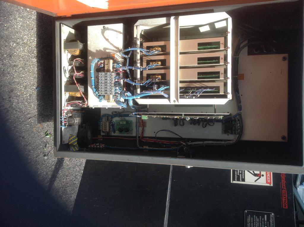
On my Bridgeport cnc from 1984 I have a power supply for the dc servos.
In line after a pair of diodes supplied by 220 single phase there is a resistor it says 1k at 1%.
In the circuit the resistor reads 34m
Am I wrong in assuming that it should read 1000 ohms? Test in the circuit I can't take it out without unsoldering it
Any body have a schematic for a drive power supply for a V2E3


Comments
Only if you knew the current, and without breaking a lead to inset the ammeter, no can do.
@jdolecki
In circuit, the resistor should never read over its stated value. It can read under due to other components.
Make sure there is no voltage present across the resistor as that can give a false resistance value.
If there is no voltage present, I'd surmise that the resistor has failed.
But the 2 fuses 220 single phase 15 amps blow immediately on power up. So I can't test anything. Live
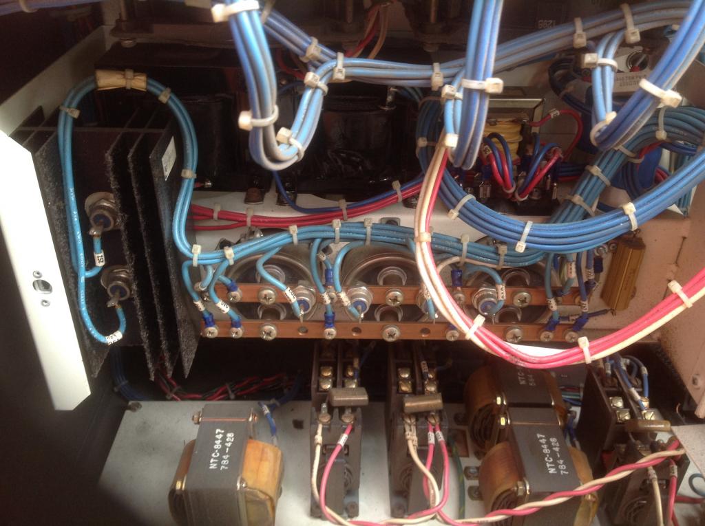
The 2 diodes on the left on the big heat sink are the line in 220v. They are connected on the back side and go to one end of that gold resistor on the right ( little rectangle box)
I assuming the both fuses blow cause of a direct short.
When diodes go bad do the just open or short to ground?
If the resistor failed would it open or short to ground?
After that resistor the wire goes to that lower lower copper bar on the 3 big caps.
The 4 diodes on the upper copper bar each supply one of the servo drives.
There are 2 transformers 2 bridge rectifiers. And anothe transforme like device but I can't think of the name of it.
Also I removed all the fuses from the power supply output that supply the machine.
So I'm assuming the fault is in there.
Also in the box is 24v for the control.
Any idea?
Thanks in advance
Your gold resistor looks like a 10 watt or 5W??? If it's designed for half power and the voltage across is 220V the formula is W=I x I x R OR sqr root of (W/R) = current.
Diodes will short or open when they go bad. The resistor you have is probably wirewound ???? so it will open when it goes bad. It's possible it might short to its case, which would then short to chassis ground--- in that case you would be pumping full 230AC into the ground and blow fuses or melt wires or blow up components.
A diode will have a forward voltage drop of 0.3V to 1.2V in one direction and be open in the other. To check the caps you'll need a cap checker-- those can loose value 300uf goes to 20uf or they short under load.
You desperately need a schematic or you can take it all apart and check components individually. If you take it apart be sure to take lots of pictures, check screws for slight differences.
You could start by disconnecting anything DC on the cap side of the rectifiers and see if the fuse blows (hopefully you have a circuit breaker)
Next disconnect the AC to the do-dad on the left with two diodes. Does it still blow? CAUTION: Never work on this while it's under power (turned on) unless you're a licensed electrician.
Dom.
There are schematics and troubleshooting procedures on the internet. The www.cnczone forums also have helpful information. Good Luck
That certainly makes sense to me. But it wouldn't hurt to remove one lead of the resistor and verify this, or just remove the resistor and verify. In circuit testing can be confusing.
That leaves you with another question, which is the nature of the failure.
In many cases, the Watt rating for the resistor might have been too low. But it could be some other fault in the circuit that needs to be addressed.
IOW, you may want to look at how to enhance the existing circuit to make it more robust. Or you might just want to replace and take a 'wait and see' approach. Both are valid.
This is a half-bridge rectifier?
You need to start this operation by constructing the circuit diagram.
If you do have an open power resistor, you should be wondering why that happened. Simply replacing it is probably not going to correct the problem, at least not for long. That type of power resistor is pretty robust and if it failed you very likely have other issues too.
I opened them all up and it still blows the fuses
34 metres?
34 milli-ohms?
m is not M, its a billion times smaller.
Until you've disconnected at least one end of the resistor I wouldn't totally trust measurements, that's a whopping
great capacitor bank there, which will be continuing to leak charge for hours are power-off.
Likely components to fail first are capacitors and diodes, not the resistor, so if it is blown there will be
something else awry too I suspect.