Eight Digit Seven-Segment Display based on MX7219
 tomcrawford
Posts: 1,129
Here is an eight digit Seven-segment display based on MX7219 that recently appeared on eBay. They mostly come from China/Hong Kong and cost from $4.00 up, a little less in fives or tens. You can find plenty of them by searching MAX7219 Digital Tube (dont know where the tube part came from).
http://www.ebay.com/itm/New-MAX7219-8-Digit-Red-LED-Digital-Tube-Display-Module-Green-Board-For-Arduino-/281347153969?pt=LH_DefaultDomain_0&hash=item418198e031
It is based on the Maxim MX7219; here is a pointer to their data sheet.
http://www.maximintegrated.com/en/datasheet/index.mvp/id/1339
This module is different from the Seven-segment module discussed in some detail in this tread. That module used just shift registers and requires constant refreshing.
http://forums.parallax.com/showthread.php/157074-7-Segement-DisplayHelp-Needed
Here is a sample driver that generates random numbers in the range +-9,999,999, and calls a PASM cog to convert to BCD and write onto a single module.
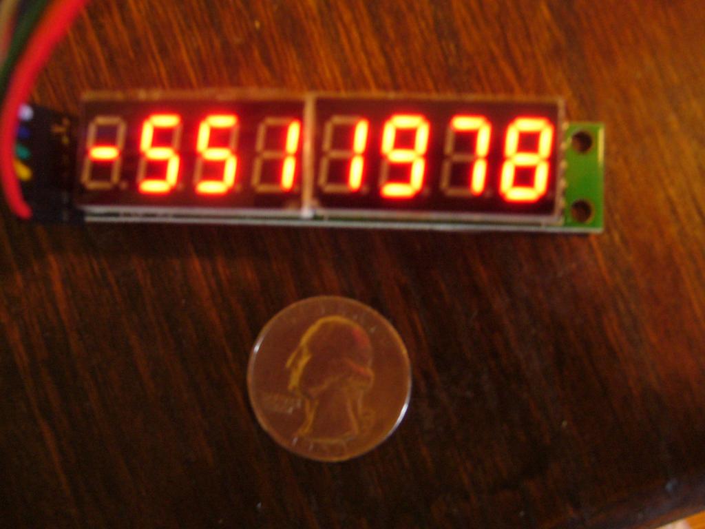
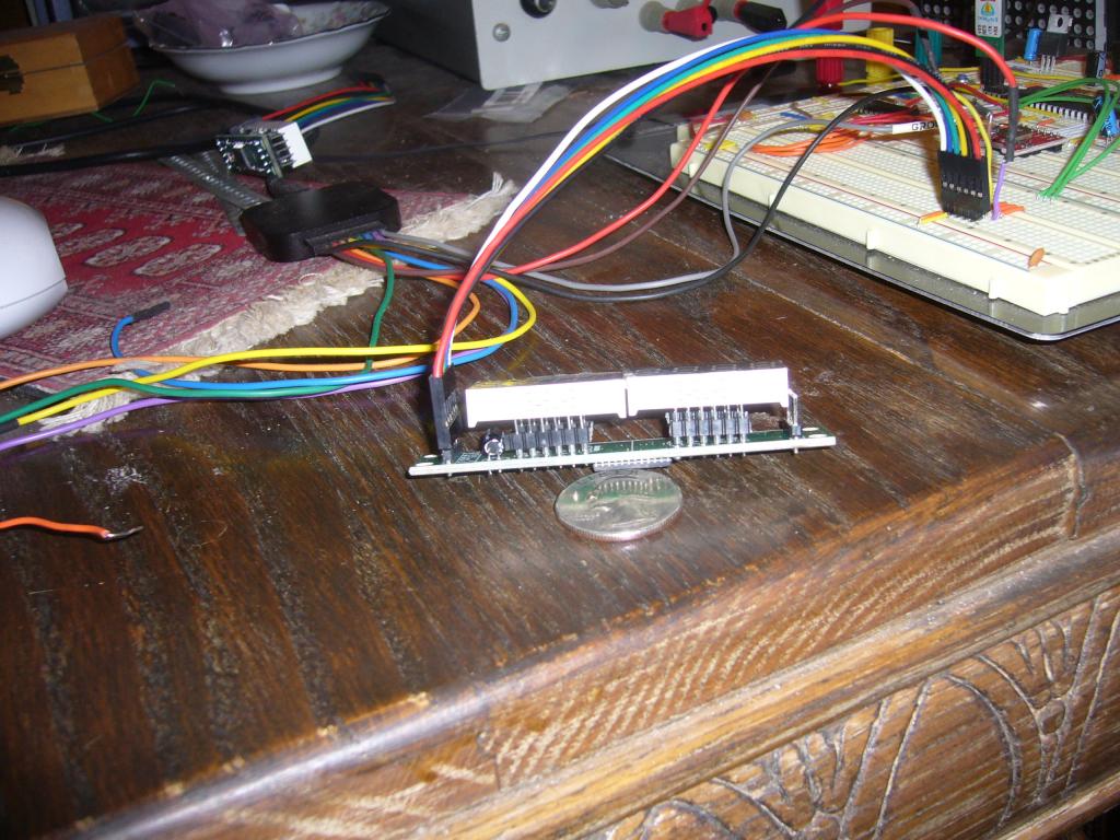
Here are a couple of photos. The eBay ads all shown the module next to a metric scale but I'm enough native U.S. to not really get a good feeling for the actual size. One picture shows a module next to a good ol' USA quarter. The other shows how the LEDs are socketed. Don't know why they did that.
I will do some fiddling to drive multiple modules and post results in this thread. tc
PS: I think I now understand why the comsub instruction happened.
http://www.ebay.com/itm/New-MAX7219-8-Digit-Red-LED-Digital-Tube-Display-Module-Green-Board-For-Arduino-/281347153969?pt=LH_DefaultDomain_0&hash=item418198e031
It is based on the Maxim MX7219; here is a pointer to their data sheet.
http://www.maximintegrated.com/en/datasheet/index.mvp/id/1339
This module is different from the Seven-segment module discussed in some detail in this tread. That module used just shift registers and requires constant refreshing.
http://forums.parallax.com/showthread.php/157074-7-Segement-DisplayHelp-Needed
Here is a sample driver that generates random numbers in the range +-9,999,999, and calls a PASM cog to convert to BCD and write onto a single module.
{Demo MX7219 Seven-segment display: Single stick}

CON

        _clkmode = xtal1 + pll16x    'Standard clock mode
        _xinfreq = 5_000_000         '* crystal frequency = 80 MHz

        CS = 0, CLK = 1, DI = 2              'Mx7219 Pins

VAR

  long  BinValue, BCDValue, random            'input, result, randomizer
  byte  Flag                                  'value input available
  long  MyParm[5]                             'passing addresses to display driver
  byte  Cog


OBJ
  pst      : "parallax serial terminal"

PUB main
    pst.Start (115_200)                                   'start up ser terminal
    pst.str(String("hello, world   "))                    'runs in cog 1
    pst.NewLine
    waitcnt(clkfreq/10 + cnt)


    MyParm[0] := @BinValue            'argument to driver cog
    MyParm[1] := @BCDValue            'value displayed
    MyParm[2] := @Flag                'valid inpiut available
    MyParm[3] := Constant((CS << 16) | (CLK << 8) | DI)   'the pins
    cog := cognew(@PCog, @MyParm)       'start up the output cog
    pst.str(String("Panel Cog: "))             '
    pst.hex(Cog,1)
    pst.NewLine
    waitcnt(clkfreq/10 + cnt)

    repeat                             'forever
      binvalue := random? // 9_999_999 'new argumwent in rangw -9,999,999..9,999,999
      Flag := 1                        'tell cog to convert
      repeat while flag <> 0           'tis he gets done
      pst.dec(BinValue)                'display input in decimal
      pst.str(string("   "))
      pst.hex(BCDValue,8)              'display my result
      pst.Newline
      waitcnt(clkfreq*5+cnt)

DAT
PCog    org   0                'This PASM cog converts bin2BCD, displays on a 7 segment panel
        mov AdPar,Par          'get the address of input parameters
        rdlong AdBin, AdPar    'Address in main memory of input argument
        add AdPar, #4
        rdlong AdBCD, AdPar    'result
        add AdPar, #4
        rdlong AdFlag, AdPar     'run flag
        add AdPar ,#4
        rdlong APins, AdPar      'get the pins
        mov Work1, APins         'copy of pins
        shr Work1, #16           'scale chip select pin number
        and Work1, #$1F          'extract just pin number
        mov CSMask, #1           'single bit mask
        shl CSMask, Work1         'scaled
        or outa, CSMask           'CS starts out high
        or dira, CSMask           'enabled
        mov Work1, APins          'clk mask is just the same
        shr Work1, #8
        and Work1, #$1F
        mov ClkMask, #1
        shl ClkMask, Work1
        or dira, ClkMask
        mov Work1, APins           'and data pin
        and Work1, #$1F
        mov DMask, #1
        shl DMask, Work1
        or dira, DMask
                                        'start up the Mx7219 Array
        mov Shifter, StDown             'shut down: get initial control
        call #Commo
        mov Shifter, Decode             'decode all digits
        call #Commo
        mov Shifter, Intens             'medium intensity
        call #Commo
        mov Shifter, ScanAll              'scan all digits
        call #Commo
        mov Shifter, Normal              'normal operation
        call #Commo

Wait    rdbyte Work1, AdFlag wz      'get the flag
        if_Z jmp #Wait               'no bits set, wait here
        rdlong BinIn, AdBin          'get input argument
        mov Accum, BinIn             'copy in case it is positive
        mov BCDOut, #$F              'decodes to blank.  Positive result
        test BinIn, SignBit wz       'see if it is negative
        if_Z jmp #L1                 'jump if positive
        mov accum, #0                 'negative input
        sub Accum, BinIn              'covert to pos
        mov BCDOut, #$A               'decodes as minus sign
L1      mov CSI, CSub                  'get nice fresh copy of cmpsub instruction
        mov DigCnt, #7                'will do seven digits
L2      shl BCDOut, #4                 'shift the current results
CSI      nop                           'becomes compare/sub instruction
        if_NC jmp #L3                 'subtract was impossible
        add BCDOut, #1                'subtract took place, increment result
        'if_Z jmp #L4                  'special case of exactly done
                                       'try uncommenting to see why this won't work
        jmp #CSI                       'continue with same subtractor
L3      add CSI, #1                    'go on to next power of 10
        djnz DigCnt, #L2              'for all seven powers of 10

'ok the conversion is complete
L4      wrlong BCDOut, AdBCD           'stash result in hub memory
        call #OneModule                'write one eight-digit module
        wrbyte zero, AdFlag            'indicate done
        jmp #Wait

OneModule mov Work1, #8                 'we will do eight registers
         mov work2, #$100                'this will be the register address in MX7219
OneML    mov Shifter, BCDOut             'into shifter
         and Shifter, #$F                'just four bits
         or Shifter, Work2               'register number
         'or shifter, #$80                'for decimal point
         andn outa, CSMask               'chip select active
         shl shifter, #16                'scale for shift
         call #Shift
         ror BCDOut, #4                  'next four bits into D3..0
                                         'MX is wired with digit 0 on the right
         or outa, CSMask                 'take away chip select (LOAD)
         add Work2, #$100                'to next register
         djnz work1,#OneML               'eight times for eight registers (digits)
OneModule_ret ret

Commo   andn outa, CSMask          'chip select: send contents of command[31..16] eight times
CommoLp Call #Shift                 'always shifts left 16 bits
        or outa, CSMask             'turn off CS
Commo_Ret   ret

Shift   mov BitC, #16                'serialize shifter[31..16] to left for 16 bits
SLoop   rol shifter, #1 wc           'get next bit into carry
        if_C or outa,DMask           'set data bit if needful
        if_NC andn outa, DMask       'or reset it
        mov MyCnt, cnt               'initialize timing for this bit
        add MyCnt, #70              'this will be data setup
        waitcnt MyCnt, #80           'data setup time, set clock high time
        or outa, ClkMask              'clock hi
        waitcnt MyCnt, #150            'clock hi period, set data hold from clock down
        andn outa, ClkMask            'clock goes low
        waitcnt MyCnt, #50             'data hold from clock low
        djnz BitC, #SLoop              'for however many bits
        andn outa, DMask              'force data low
Shift_Ret  ret                        'and return


StDown  long $0C00_0000          'shutdown  Note prescaled for shift routine
Decode  long $09FF_0000          'decode all digits
Intens  long $0A02_0000          'modest brightness
ScanAll long $0B07_0000          'scan all digits
Normal  long $0C01_0000          'normal operation


Ten6    long 1000000
Ten5    long 100000
Ten4    long 10000
Ten3    long 1000
Ten2    long 100
Ten1    long 10
Ten0    long 1

SignBit long $8000_0000
Zero    long 0

CSub    cmpsub Accum, Ten6 wc, wz    'fresh copy of compare, subtract

BinIN   res                      'input in Binary
BCDOut  res                      'Output in signed BCD

AdPar   res                      'address of parameter list
AdBCD   res                      'result
AdFlag  res                      'run flag
AdBin   res                      'input
Accum   res                      'running remainder

APins   res
CSMask  res                       'pin masks
ClkMask res
DMask   res
Work1   res                     'couple of COG general working registers
Work2   res
BitC    res                     '16 bits in each register
Command res                     'used for global commands
Shifter res                      'variable being shifted
MyCnt   res                      'used to time shifters
DigCnt  res                      'counts the digits
        fit 150
Here are a couple of photos. The eBay ads all shown the module next to a metric scale but I'm enough native U.S. to not really get a good feeling for the actual size. One picture shows a module next to a good ol' USA quarter. The other shows how the LEDs are socketed. Don't know why they did that.
I will do some fiddling to drive multiple modules and post results in this thread. tc
PS: I think I now understand why the comsub instruction happened.


Comments
Thanks for posting your code.
http://youtu.be/JH0_inuzoO4
I had tried "daisy-chaining" the sticks, but there was way too much VCC drop to do more than a couple. So I connected them in parallel, so to speak, with common clock and data, separate chip selects.
You can use the MUXC instruction to replace these two lines of code:
if_c            or      outa, dmask
        if_nc           andn    outa, dmask
with...
Perhaps my wife was right about reading the Prop Manual in bed after all.
I should point out that pull-ups on the CS pin(s) are really really Good. I think the MX7219 gets very confused if CS is undefined when power comes on and goes into some odd state a lot like lamp test except it ignores anything you tell it. Seems to me that Duane Degn and I found this during the MX7219 8x8 module days. I use 20K to +5V and that seems to work. Also 20K to +5V shouldn't fry the prop pin.
All BS2 examples use 4 digits with MAX7219, had no luck running 8 digits on it.
This should get you started. Remember, DIG is your friend.
' {$STAMP BS2} ' {$PBASIC 2.5} ' {$PORT COM14} Clk PIN 10 DIN PIN 12 CS PIN 11 SWord VAR Word 'word which is shifted out to 7219 SWHi VAR SWord.HIGHBYTE SWLo VAR SWord.LOWBYTE Digit VAR Word begin: HIGH CS 'normally not selected LOW CLK 'make these outputs LOW DIN SWord = $0C01 'shutdown register, normal operation GOSUB DMX7219 SWord = $09FF 'decode register, decode GOSUB DMX7219 SWord = $0B07 'scan limit, all rows GOSUB DMX7219 SWord = $0A08 'intensity register, medium GOSUB DMX7219 Drive: 'display seven thru zero FOR Digit = 0 TO 7 'go from right to left SWHi = (Digit +1) SWLo = Digit GOSUB DMX7219 NEXT END DMX7219: 'drive MX 7219 LOW CS 'enable SHIFTOUT DIN, CLK, MSBFIRST, [SWord \16] 'shift out 16 bits HIGH CS 'it loads and executes RETURNI've set decide register to 0X00 and now assigning varios data to Sword variable displays various segments lit, however, it is hard to determine,which digit does what.
The high order byte of SWORD specifies which digit is written (1..8) and the low order byte specifies which segments are lit. Be systematic and write values with a single bit set in the SWLO field, one at a time, and write down on a piece of paper which bit controls which segment. Then decide which combinations are pleasing.
Or you could look at the data sheet, Table 6 on page 8.
tc
The "Drive" portion works fine, I see "0 1 2 3 " on display (using 4 digit right now)
but the code below works not as planned. Even if SWLO=%00000001, 4 segments lit up - G segments in char 2,3,4 and B segment in char 4. If the wiring was incorrect, then "0 1 2 3" should not be displayed, right?