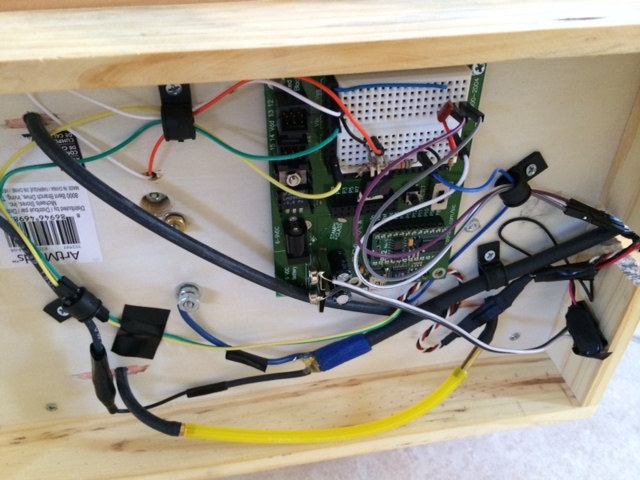
Basic stamp 2 going heywire
Hello all,
I have made a small model engine which I am using basic stamp 2 to control the RPM using solenoid which will act as a governor. The engine also use CDI module to provide ignition to the spark plug. The CDI is not in any way connected to basic stamp and work independently. The original code didn't work, there fore I made the code very simple to see if something else is the issue.
When the engine is not running the below code works perfectly. The solenoid become active for 3 secs and inactive for 2 sec with no issues.
However when the engine is running, the solenoid is either become active and stays active continuous or never becomes active at all.
' {$STAMP BS2}
' {$PBASIC 2.5}
Gov PIN 14 'if this pin goes high, it will activate the solenoid
do
HIGH Gov
PAUSE 3000
LOW Gov
PAUSE 2000
LOOP
So this code works as long as the engine is not running.
so I am thinking the following
1.maybe the engine vibration interfere with the basic stamp? From picture you can see the stamp is connected at the bottom of the engine panel
2.maybe the high voltage from the CDI interfere with the stamp?
Here is the video of the engine running
https://www.youtube.com/watch?v=SpEAWje8n5Y
Any idea if the 2 above case could cause the stamp to go haywire?


Comments
Have you scoped out the BS2's power supply? How are you powering the BS2 exactly?
Ken Gracey
2) High voltage from the CDI might indeed be interfering with the Stamp. Specifically, electrical noise can cause the Stamp to reset and the program to start over from the beginning. You would need to identify what wires in the picture carry high voltage or carry power to the CDI. Typically, you would shield the logic circuitry (the Stamp board and what's connected to it) and add filtering to the power supplied to the Stamp board.
As Per Mr. Gracey's comment, you need to observe the Stamp's supply lines, and checking the data lines would be a good idea also. You'll be looking for large amounts of noise.
Anything other methods of debug will be "working in the dark", and a guess at best.
Did you use shielded wire to connect pin 14 to the solenoid?
From the youtube link I understand the solenoid locks the push rod so the valve stays open and the engine stops.
The issue is fixed. main reason to the problem was that the battery was attached to the CDI unit. Once I removed the battery away, then things started to work.
you can see a video as how the solenoid works
https://www.youtube.com/watch?v=Un0HZwI8pwg&list=UUL8gj_06zIsMRLY-U6zQItA
The logic is I have a hall sensor that measures the RPM, if RPM goes above 2200, then it will activate the solenoid for 1 sec. Now that everything is working I can place a better logic.
' {$STAMP BS2}
' {$PBASIC 2.5}
Gov PIN 14
SpeedIn PIN 3
SensorPulses VAR Byte
rpm VAR Word
DO
LOW Gov
rpm = 0
Capture CON 1000
SensorPulses = 0
COUNT SpeedIn, Capture, SensorPulses
rpm = (SensorPulses * 60)
IF rpm > 2200 THEN
HIGH Gov
PAUSE 1000
ENDIF
LOOP