Shop OBEX P1 Docs P2 Docs Learn Events
2-Axis Joystick — Parallax Forums

2-Axis Joystick

stx2006stx2006 Posts: 20
edited 2014-09-16 05:09 in BASIC Stamp
I bought the 2-Axis Joystick from Parallax to use to control my robot. Question is. How do I wire it up? I followed the KickStart guide on the website. But I can't seem to get it to ever work. I was wondering if someone could help me out.

Also is there anything different I need to do if I wire it up and it's on sitting on the breadboard?
[COLOR=#000000]' {$STAMP BS2}[/COLOR]
' {$PBASIC 2.5}UDPin   CON   8LRPIn   CON   9LR      VAR   WordUD      VAR   WordDO  HIGH LRPin  PAUSE 2  RCTIME LRPin, 1, LR  HIGH UDPin  PAUSE 2  RCTIME UDPin, 1, UD  DEBUG HOME, "UD = ", DEC UD, ", LR = ", DEC LR, CLREOL  PAUSE 50 [COLOR=#000000]LOOP
[/COLOR]

That's the code I'm using. It's the code on the KickStart guide.

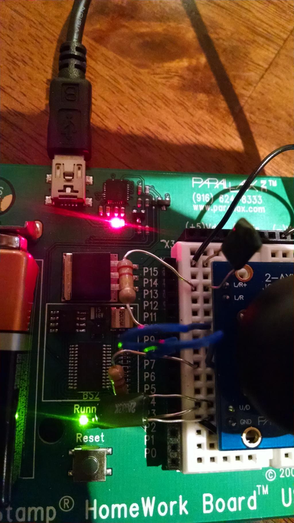
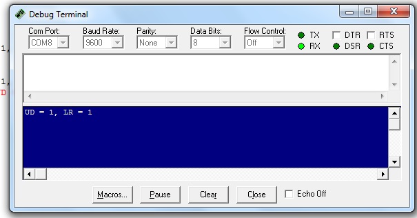
Here's some pictures on how I have it wired up and what the Debug window looks like when I try to run it.
1024 x 1819 - 202K
605 x 316 - 46K

Comments

  • PublisonPublison Posts: 12,366
    edited 2014-09-10 17:34
    It's hard to see if the connections are correct. Could you see if you could get a better picture with more light?
  • Duane DegnDuane Degn Posts: 10,588
    edited 2014-09-10 17:42
    I don't think you have the joystick wired correctly. It looks like the top capacitor is connected to ground and "L/R+" and from the Learn tutorial, it looks like it should connect with "L/R".

    I think you should move the lower lead of the top cap down one row. The top lead of the top resistor will also need to be moved one row down.

    I might not be seeing how your board is wire correctly do to angle of the photo, but if I'm seeing what I think I'm seeing, I think changing the wiring should help.
  • stx2006stx2006 Posts: 20
    edited 2014-09-11 05:25
    Here's a new picture. Maybe the light it better on this one.
    1024 x 1819 - 209K
  • PublisonPublison Posts: 12,366
    edited 2014-09-11 07:05
    stx2006 wrote: »
    Here's a new picture. Maybe the light it better on this one.

    Thanks for the better picture.

    As Duane mentioned. the top connection should got to L/R not L/R+ according to the Learn Tutorial.

    Also on the bottom connection, the black wire, (which I assume is GND/VSS) should move down one hole to GND. The resistor lead should also move down one hole to the U/D pin on the joystick.

    Hope that helps.

    EDIT: Just saw one more mis-wire. The top blue wire should move up one hole to connect to the resistor. ( (The connections are horizontal on a breadboard).

    Check out this tutorial that Parallax put together:

    http://www.learn.parallax.com/breadboarding
  • stx2006stx2006 Posts: 20
    edited 2014-09-11 07:14
    OK thanks. I'll try that on lunch break.

    The picture for the BS on the Kick Start page is misleading because mine doesn't have the slot of holes on the breadboard below P0.
  • PublisonPublison Posts: 12,366
    edited 2014-09-11 07:33
    Are you working off of this picture?

    Homework Board.jpg
    363 x 340 - 95K
  • stx2006stx2006 Posts: 20
    edited 2014-09-11 07:35
    Yes I am.

    .
    .
    .
  • PublisonPublison Posts: 12,366
    edited 2014-09-11 08:13
    I'm guessing the author used a generic breadboard drawing for the graphic. It really doesn't matter, since there is no direct connection between the white breadboard and the black P0-P15 sockets.
  • stx2006stx2006 Posts: 20
    edited 2014-09-11 09:01
    Still a no go. I just don't see what I'm doing wrong. It looks just like the pic on the website..
    1024 x 1819 - 234K
    1024 x 576 - 110K
  • PublisonPublison Posts: 12,366
    edited 2014-09-11 09:36
    Try and copy/Paste this code in the Basic Stamp Editor:
    ' {$STAMP BS2}' {$PBASIC 2.5}


    UDPin   CON   8
    LRPIn   CON   9
    LR      VAR   Word
    UD      VAR   Word
    
    
    DO
      HIGH LRPin
      PAUSE 2
      RCTIME LRPin, 1, LR
      HIGH UDPin
      PAUSE 2
      RCTIME UDPin, 1, UD
      DEBUG HOME, "UD = ", DEC UD, ", LR = ", DEC LR, CLREOL
      PAUSE 50
    LOOP
    

    Your code didn't show up correctly in your first post.

    Or use the attached file.

    You might also want to check two other pins on the BS2.

    Change PINS 8,9 to 10,11 and change the wiring accordingly. This will check if the pins on the the BS2 were damaged.

    The code tags do not seem to be working.
  • stx2006stx2006 Posts: 20
    edited 2014-09-11 10:02
    What's the odds of maybe a bad capacitor? Maybe even a bad joystick? I know the BS cant be bad because I can load other programs onto it and it works.
  • Courtney JacobsCourtney Jacobs Posts: 903
    edited 2014-09-11 10:16
    It looks like you have red-red-yellow resistors (220k-ohm), but the exercise calls for red-red-brown resistors (220-ohm).

    Try double-checking your capacitor and resistor values.
  • PublisonPublison Posts: 12,366
    edited 2014-09-11 10:21
    It looks like you have red-red-yellow resistors (220k-ohm), but the exercise calls for red-red-brown resistors (220-ohm).

    Try double-checking your capacitor and resistor values.

    Excellent call! I thought it was my tied old monitor.
  • stx2006stx2006 Posts: 20
    edited 2014-09-12 05:01
    It looks like you have red-red-yellow resistors (220k-ohm), but the exercise calls for red-red-brown resistors (220-ohm).

    Try double-checking your capacitor and resistor values.

    Good catch! I didn't even notice that when I bought them. I'll go get the right ones and try that!
  • stx2006stx2006 Posts: 20
    edited 2014-09-14 17:42
    Just an update! Once I got the right ones it's working great now! Now I just gotta figure out how to make it control things. :-D
  • GenetixGenetix Posts: 1,753
    edited 2014-09-14 21:55
    If you have some XBee modules and a Boe-Bot then try the project on page 135.
    http://www.parallax.com/sites/default/files/downloads/122-32450-XBeeTutorial-v1.0.1.pdf
  • stx2006stx2006 Posts: 20
    edited 2014-09-16 05:09
    Genetix wrote: »
    If you have some XBee modules and a Boe-Bot then try the project on page 135.
    http://www.parallax.com/sites/default/files/downloads/122-32450-XBeeTutorial-v1.0.1.pdf

    I don't have that. I don't like buying "kits"
Sign In or Register to comment.