

Arlo Power Distribution Board Assembly
Here is my review of the Arlo Power Distribution Board assembly. It won't be nearly as long or detailed as my Building Arlo review. Mostly because there wasn't that much to it, and also because once you get a hot soldering iron in your hands you don't really want to set it down to pick up a camera every few minutes. ")
As for the difficulty and level of skill required, here is my take.
This is only the second through board soldering project I have ever done in my life, so that should tell you something.
I only get my soldering iron out about once a year.
I've done things like install car alarm and remote starter systems, so I'm comfortable with the soldering iron, but again, putting wires together or tacking connectors on the end of wires is not the same as through board.
So my advice to anyone else is that this is very easy. If you have never done any through board soldering before, just get a solder board and practice soldering some diodes to it for a while until you get comfortable. You don't want to be doing your first ever through board solder joint on this, but this is certainly a fine first project. You just want to practice a little first. Soldering is like driving a stick shift. If you are smart you can read how to do it, but you'll need to practice a little before you become comfortable enough to do it well.
There are also some good online tutorials on how to solder and what equipment you will need.
I can post a link to the site I found very helpful, but it is on another company's site, so I wasn't sure if I should. Google will find it quickly though if you look up soldering.
So here is my experience and my comments:
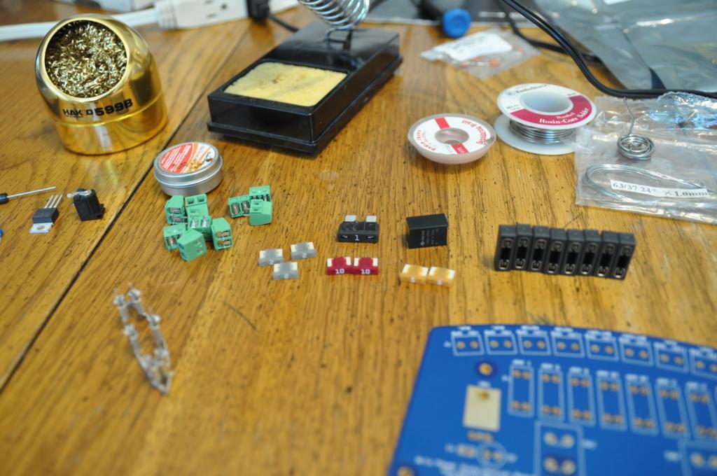
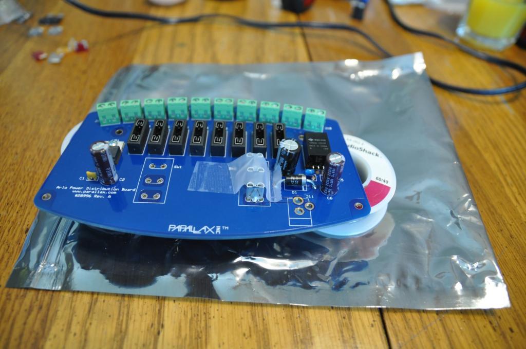
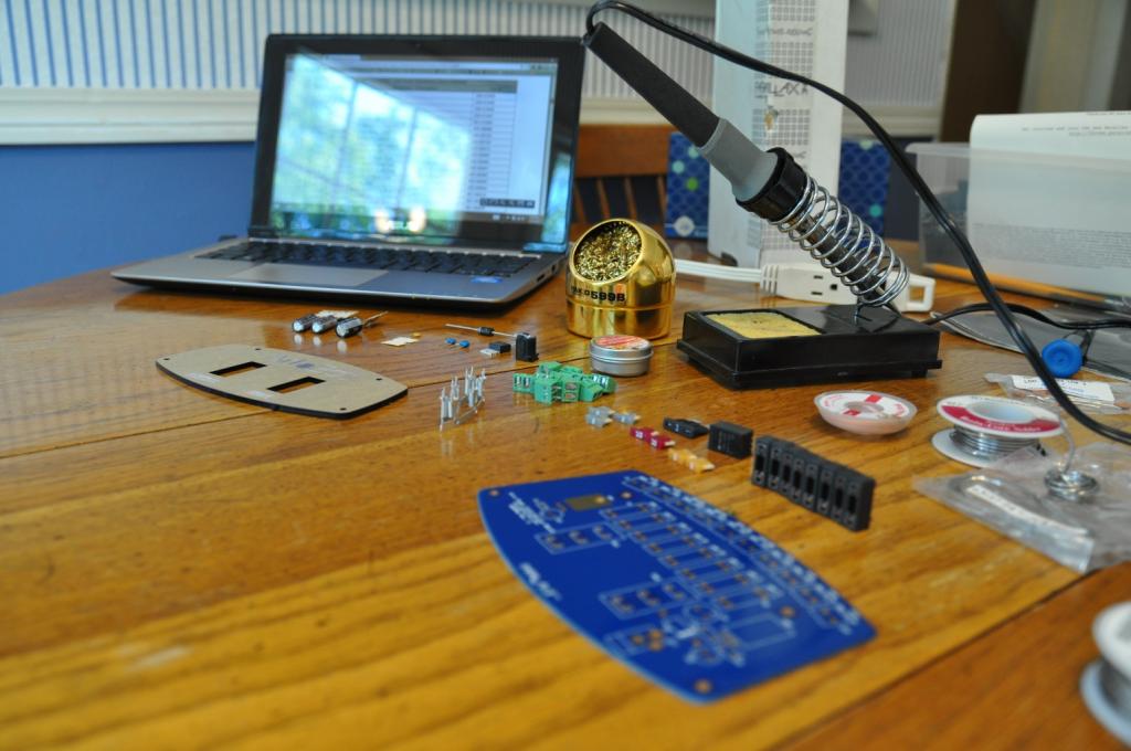
Here are all of the parts from the exciting new kit laid out and ready to go with my tools:

The kit contains a lot of little part, and through Parallax magic that is only rivaled by toy makers, they somehow never miss a piece!
One thing you will be presented with is an array of capacitors. These are the only "scary" part, because they aren't all marked in a way that is clear to the novice, and the instructions use words like "explode."
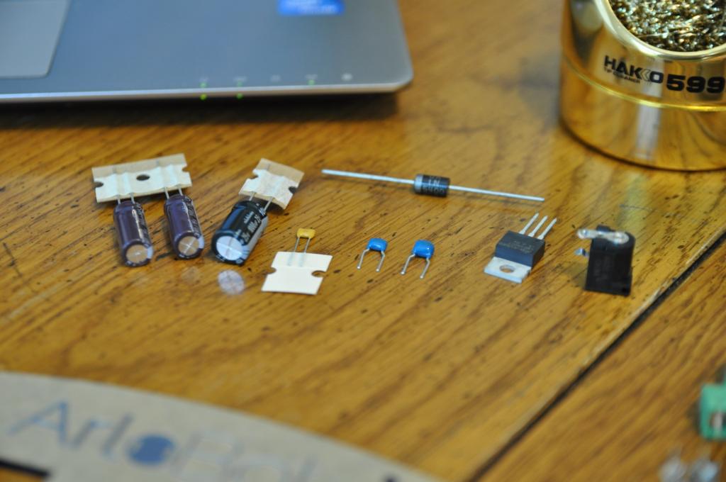
It would be beneficial if the number printed on the side of the C5 and C4 capacitors was included. Their size difference is not as great as it appears in the instruction page. I had to do some web searching and reading to satisfy myself that I understood the numbers printed on the capacitors well enough to be convinced I had the right one in the right place.
Also, for the polarized capacitors the negative side of the capacitor has a "0" on it, not a "negative (-) sign". Also I think all polarized capacitors are made with the positive lead longer than the negative one, which was not mentioned in the instructions.
And then you can see that things went very quickly before I set down the iron long enough to take another picture:
Pay close attention to getting the fuse holders flat. My first one ended up raised a bit, and getting all four posts soft enough at the same time takes some quick work. It isn't hard to get them all flat, it is just easy to think they are held fast and find out they were not if you don't pay attention.
The screw terminals are amazingly easy to get to sit just right in that round arc. I only had to redo one of them, and in the end only one is a little off

but you will not notice this once it is installed.
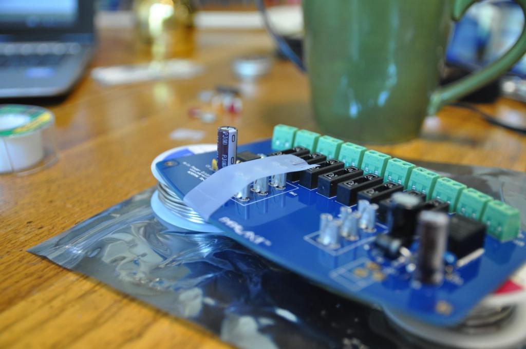
The tape trick to hold down the blade terminals wasn't working for me on one side, because the center blade was shorter than the rest. It is easy for this to happen when clipping them from the strip, so I put the tape sideways and used a toothpick to press it down between the terminals and the capacitors
Which worked perfectly, and the tape trick worked exactly as documented on the other side:
One thing that is missing from the instructions is that there is no mention in the document of installing the Jack J11.
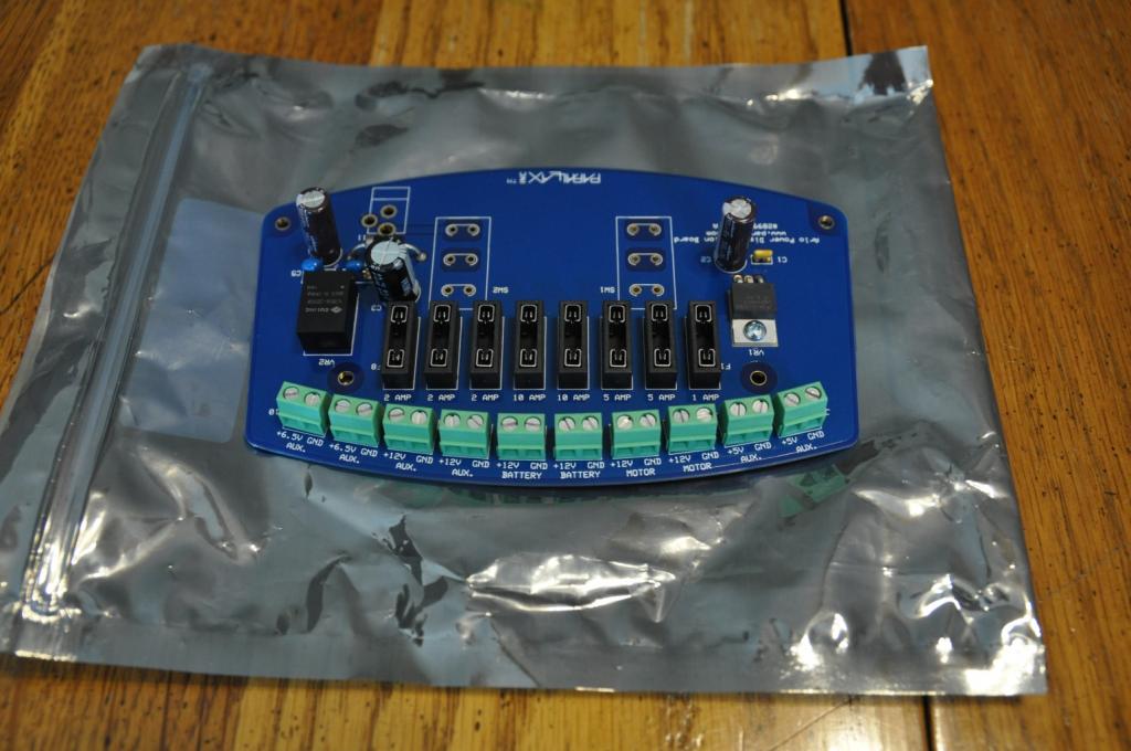
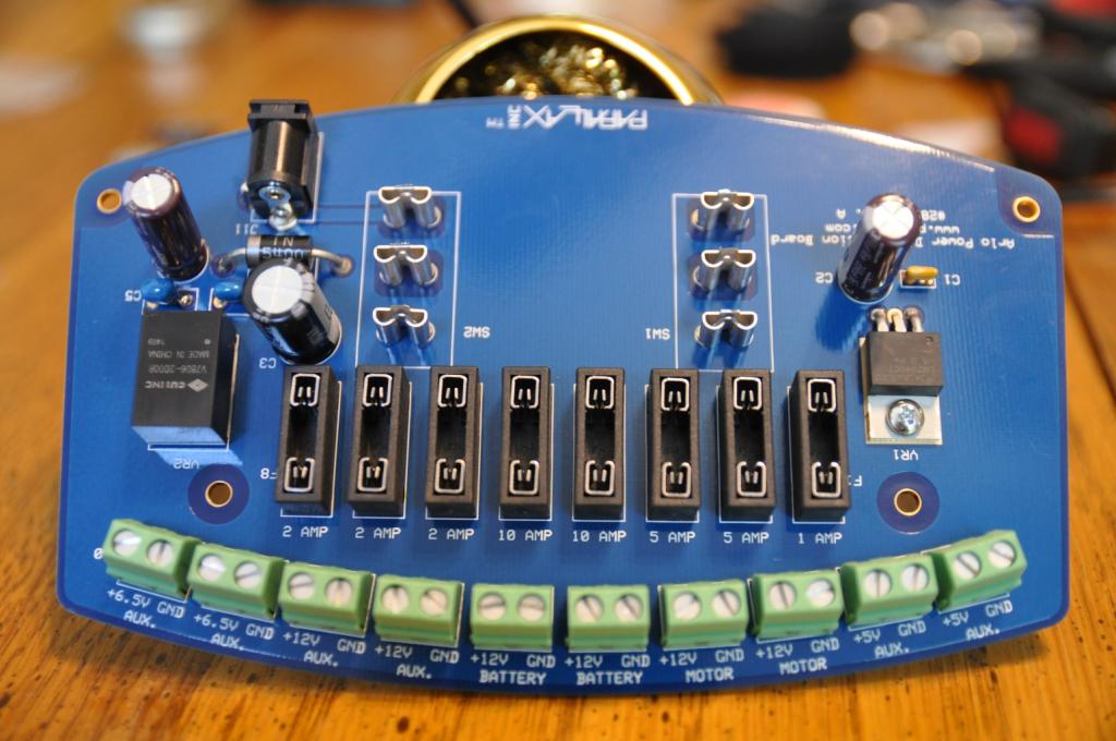
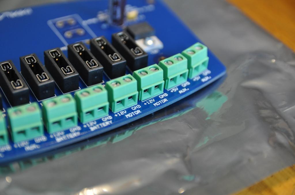
Here is my finished board from the top
And here is my solder work from the bottom. Remember, I only get out the soldering iron about once a year and this is only my second through board project ever, the first being several years ago
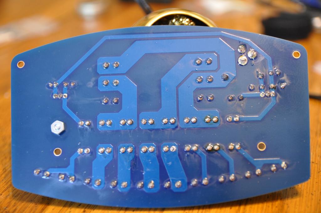
So if I can do this, you can to!
If anyone wants higher resolution or closer pictures for inspection and grading let me know. :-P
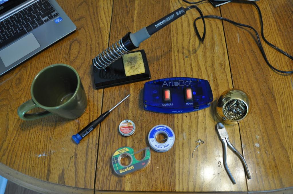
Here is my finished board with all of the tools I used

The soldering iron is just a basic 40 watt iron from Radio Shack. A variable iron and a finer tip than I had would be helpful, but this did the job for me, again proving that this is an easy project that can be done with basic equipment.
Another thing I feel is missing from the manual is a clear picture or two of the finished board from the top to compare to make sure everything is on and in the right place.
Since I'm about at my per post picture limit I'll post a bunch of clear pictures of my finished board in the next post.
Continued in next post . . .
As for the difficulty and level of skill required, here is my take.
This is only the second through board soldering project I have ever done in my life, so that should tell you something.
I only get my soldering iron out about once a year.
I've done things like install car alarm and remote starter systems, so I'm comfortable with the soldering iron, but again, putting wires together or tacking connectors on the end of wires is not the same as through board.
So my advice to anyone else is that this is very easy. If you have never done any through board soldering before, just get a solder board and practice soldering some diodes to it for a while until you get comfortable. You don't want to be doing your first ever through board solder joint on this, but this is certainly a fine first project. You just want to practice a little first. Soldering is like driving a stick shift. If you are smart you can read how to do it, but you'll need to practice a little before you become comfortable enough to do it well.
There are also some good online tutorials on how to solder and what equipment you will need.
I can post a link to the site I found very helpful, but it is on another company's site, so I wasn't sure if I should. Google will find it quickly though if you look up soldering.
So here is my experience and my comments:
Here are all of the parts from the exciting new kit laid out and ready to go with my tools:
The kit contains a lot of little part, and through Parallax magic that is only rivaled by toy makers, they somehow never miss a piece!
One thing you will be presented with is an array of capacitors. These are the only "scary" part, because they aren't all marked in a way that is clear to the novice, and the instructions use words like "explode."
It would be beneficial if the number printed on the side of the C5 and C4 capacitors was included. Their size difference is not as great as it appears in the instruction page. I had to do some web searching and reading to satisfy myself that I understood the numbers printed on the capacitors well enough to be convinced I had the right one in the right place.
Also, for the polarized capacitors the negative side of the capacitor has a "0" on it, not a "negative (-) sign". Also I think all polarized capacitors are made with the positive lead longer than the negative one, which was not mentioned in the instructions.
And then you can see that things went very quickly before I set down the iron long enough to take another picture:
Pay close attention to getting the fuse holders flat. My first one ended up raised a bit, and getting all four posts soft enough at the same time takes some quick work.
The screw terminals are amazingly easy to get to sit just right in that round arc. I only had to redo one of them, and in the end only one is a little off
but you will not notice this once it is installed.
The tape trick to hold down the blade terminals wasn't working for me on one side, because the center blade was shorter than the rest. It is easy for this to happen when clipping them from the strip, so I put the tape sideways and used a toothpick to press it down between the terminals and the capacitors
Which worked perfectly, and the tape trick worked exactly as documented on the other side:
One thing that is missing from the instructions is that there is no mention in the document of installing the Jack J11.
Here is my finished board from the top
And here is my solder work from the bottom. Remember, I only get out the soldering iron about once a year and this is only my second through board project ever, the first being several years ago
So if I can do this, you can to!
If anyone wants higher resolution or closer pictures for inspection and grading let me know. :-P
Here is my finished board with all of the tools I used
The soldering iron is just a basic 40 watt iron from Radio Shack. A variable iron and a finer tip than I had would be helpful, but this did the job for me, again proving that this is an easy project that can be done with basic equipment.
Another thing I feel is missing from the manual is a clear picture or two of the finished board from the top to compare to make sure everything is on and in the right place.
Since I'm about at my per post picture limit I'll post a bunch of clear pictures of my finished board in the next post.
Continued in next post . . .
1024 x 680 - 83K

1024 x 680 - 97K

1024 x 680 - 69K

1024 x 680 - 85K
1024 x 680 - 59K

1024 x 680 - 83K

1024 x 680 - 65K

1024 x 680 - 93K

1024 x 680 - 73K
1024 x 680 - 115K
Comments
Here are several pictures of the finished board. I have a nice lens for my camera, but I'm not a photographer.
Better lighting would probably help.
The fuses were very hard to insert. What worked for me was to put them in at a bit of an angle to get one side in just a little and then it was easier to press them in the rest of the way. If you put the one side in too far though they will bind, so take your time.
The switches went in beautifully.
Before hooking up anything I connected one battery at a time and tested all output voltages on every terminal to confirm the voltage level and polarity.
I wondered if this would prevent a rear PING/IR sensor from mounting, but it fits just fine:
Finally here is ArloBot with his new power supply!
This was a fun project. While it would seem nice to be able to buy a "bolt on" solution, there is a lot of benefit to doing your own soldering. It provides some learning, it gives a person a lot of pride in his work, and very importantly, as you work on electronic projects you are bound to come upon some nifty thing you want to add to your robot someday that requires soldering. If everything you did was "bolt on" or breadboard work, you may be hesitant to buy it, but now that you've done this, you won't be shy about taking on other soldering projects. You might even find yourself turning some of your breadboard projects into solder board projects some day!
As to the value, I think the price is very good. I haven't priced out all of the parts, but my guess is they would be at least half the cost of the kit. Add to that the engineering and safety and I think it is a great value. I spent a lot of time trying to design my own power supply for the ArloBot before this was announced and it would not have been nearly as nice. Someone who routinely engineers electronic projects could certainly roll their own, but for those of us that are not experienced, the engineering here and the pre made board are wonderful.
I especially like the comments on the Documentation - we'll incorporate the suggestions into an upcoming revision.on the Product Doc. Since it's such a new product, it's great to have a "Guinea Pig".such as yourself - giving us some near real-time feedback early in the product's history!
As Whit says - keep us posted on what you're doing with Arlo!
-MattG
One thing I forgot to mention is that the kit did not include a cable to connect the power supply to the Activity Board. What I did as cut the wire off of a AA battery holder for the Activity Board.
I realize that this power supply is not specifically for the Activity Board, and that you could also be accused of not providing ALL of the wires to connect the motors, HB25's, batteries, etc.
However, since this power supply does specifically supply 6.5 volts, presumably for the Activity Board, and since it goes on an ArloBot, which has holes drilled for the Activity Board, and for which there is code to control the ArloBot, it would be a nice finishing touch to include either a wired connector for the Activity Board's plug, or at least the barrel connector, or even just put a link to such an item on the order page for the power distribution board.
It is just another one of those "in between" bits, as I mentioned on the AlroBot, that would flush out the "kit" and make it require less runs to Radio Shack.
EDIT: Or just tell people to buy a AA battery holder and cut the cable off.