

KNEX Motor Sensor for Basic Stamp Homework Board Microcontroller
 KylePKing
Posts: 44
KylePKing
Posts: 44
I am running a microcontroller to turn a KNEX AC motor (12 V, 500 mA) On and OFF via two sets of IR sensors from Radioshack.
This powers a KNEX roller coaster train. With multiple cars, this stops the motor after exiting lift hill until another point on the track before train passing another sensor IR beam zone and initiating POWER ON for the motor. This creates "Buffer Zone" for no collision of multiple trains on one track.
The code is PBASIC.
The microcontroller works very well.
Currently, the default is POWER OFF for the motor when unplugged and plugged back into the AC outlet on the wall. Then, the starting sensors (MOTOR ON) are passed by a roller coaster vehicle to initiate the motor.
However, I want the default POWER ON for the motor when unplugged and plugged back into the AC outlet on the wall.
This way, if the train is on the lift hill, the train will have POWER ON automatically with no Sensor Beam interruption necessary. As the train exits lift hill, it hits Sensors OFF IR Beam. Later along course of track, it hits Sensors ON IR Beam. Train behind it now has ability to climb lift hill via Motor.
Please help. Does the PBASIC code need to change? What needs to change?
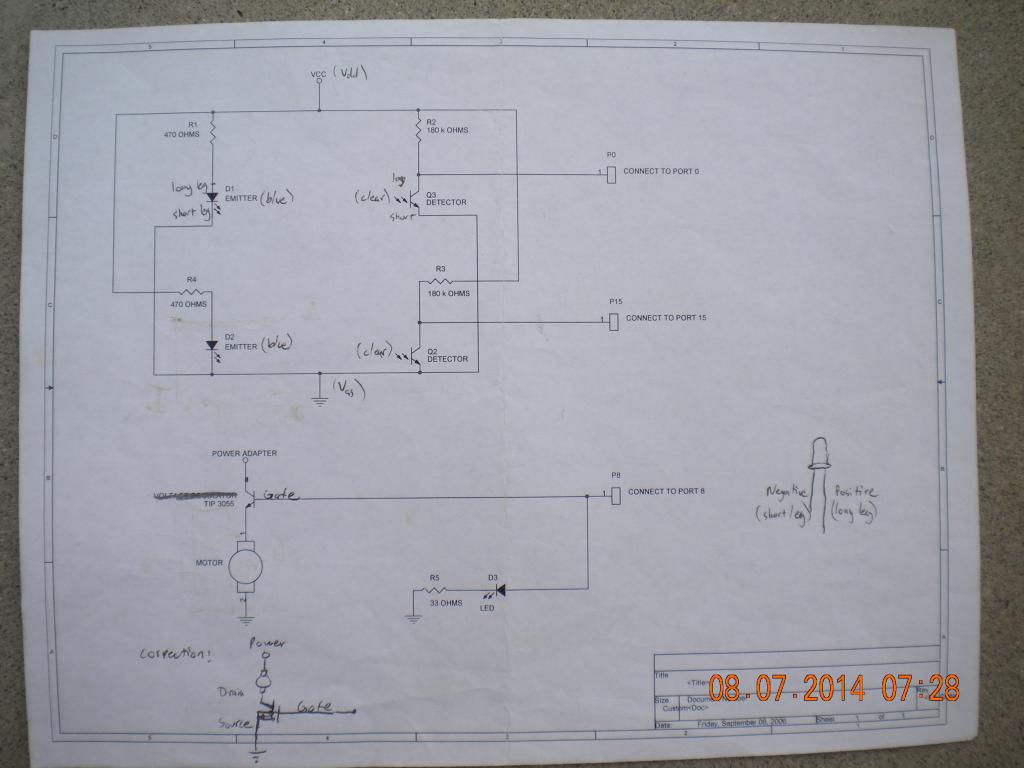
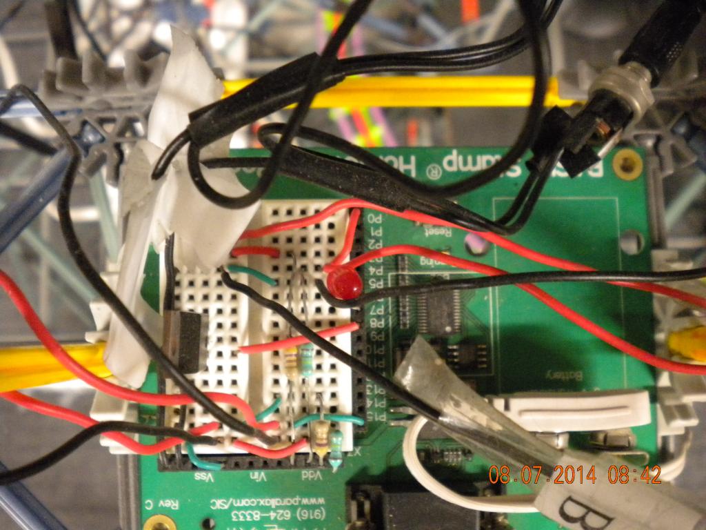
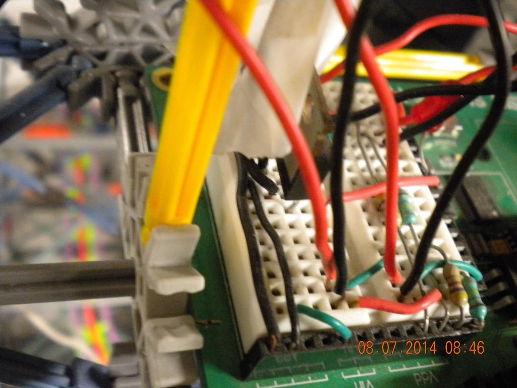
Attached are photos, schematics, and breadboard terminal numbers/labels for wiring connections.
Thank you.
Here is the PBASIC Code:
Programmed in PBasic
{$STAMP BS2}
sensor1 VAR IN0
sensor2 VAR IN15
motor CON 8
INPUT 0
INPUT 15
OUTPUT 8
loop:
LOW motor
IF sensor1 = 1 THEN start
GOTO loop
start:
HIGH motor
IF sensor2 = 1 THEN loop
GOTO start
END
Here are the Breadboard Terminals
Motor:
VSS 4, P9 Black Wire High #
Adaptor Plug:
VSS 4, P8 Black Wire Low #
Start Sensors (Motor On):
Clear Detector: VDD 2 Positive Wire, P4
Negative Wire, P5
Blue Emitter: VSS2 Positive Wire, P3
Negative Wire, P4
Ending Sensors (Motor Off):
Clear Detector: VDD 5 Positive Wire, P15
Negative Wire, X4
Blue Emitter: VSS2 Positive Wire, P15
Negative Wire, X4
Note:
Positive Wire is Red.
Negative Wire is Black.
This powers a KNEX roller coaster train. With multiple cars, this stops the motor after exiting lift hill until another point on the track before train passing another sensor IR beam zone and initiating POWER ON for the motor. This creates "Buffer Zone" for no collision of multiple trains on one track.
The code is PBASIC.
The microcontroller works very well.
Currently, the default is POWER OFF for the motor when unplugged and plugged back into the AC outlet on the wall. Then, the starting sensors (MOTOR ON) are passed by a roller coaster vehicle to initiate the motor.
However, I want the default POWER ON for the motor when unplugged and plugged back into the AC outlet on the wall.
This way, if the train is on the lift hill, the train will have POWER ON automatically with no Sensor Beam interruption necessary. As the train exits lift hill, it hits Sensors OFF IR Beam. Later along course of track, it hits Sensors ON IR Beam. Train behind it now has ability to climb lift hill via Motor.
Please help. Does the PBASIC code need to change? What needs to change?
Attached are photos, schematics, and breadboard terminal numbers/labels for wiring connections.
Thank you.
Here is the PBASIC Code:
Programmed in PBasic
{$STAMP BS2}
sensor1 VAR IN0
sensor2 VAR IN15
motor CON 8
INPUT 0
INPUT 15
OUTPUT 8
loop:
LOW motor
IF sensor1 = 1 THEN start
GOTO loop
start:
HIGH motor
IF sensor2 = 1 THEN loop
GOTO start
END
Here are the Breadboard Terminals
Motor:
VSS 4, P9 Black Wire High #
Adaptor Plug:
VSS 4, P8 Black Wire Low #
Start Sensors (Motor On):
Clear Detector: VDD 2 Positive Wire, P4
Negative Wire, P5
Blue Emitter: VSS2 Positive Wire, P3
Negative Wire, P4
Ending Sensors (Motor Off):
Clear Detector: VDD 5 Positive Wire, P15
Negative Wire, X4
Blue Emitter: VSS2 Positive Wire, P15
Negative Wire, X4
Note:
Positive Wire is Red.
Negative Wire is Black.
1024 x 768 - 63K

1024 x 768 - 129K
1024 x 768 - 112K

1024 x 768 - 93K

1024 x 768 - 92K

1024 x 768 - 73K

1024 x 768 - 103K

1024 x 768 - 100K
1024 x 768 - 92K

1024 x 768 - 85K
Comments
Basically, when no power from AC outlet. I then plug in the AC outlet for the motor, then the lift hill works, regardless of sensors and train positions. AFterward, the train in the lead goes along course, exits lift hill, then interrupts the IR sensors (emitter and detector from radioshack). Once the train travels a certain distance, train interrupts another IR sensors (emitter and detector from radioshack) and the Motor initiates again.
If AC cord is pulled out and a train is stopped on lift hill and hits no sensors, the train stalls on the lift hill. There is NO Default POWER. I want to change that.
I want the train on the lift hill. Pull AC cord out of wall. Put AC cord into wall. And, the train goes up the lift hill because the PBasic program has Default POWER ON for the motor.
When the train is on the lift hill, it all depends on the other train. If the lead train makes it to the point of the other sensor, the lift hill initiates. However, if AC wall outlet is disengaged after train hits second sensor zone, there is a lift hill stall for the previous motor. When AC outlet is engaged, the second sensor zone (down the track) initiates POWER ON. When AC outlet is engaged, the first sensor zone (immediately after lift hill) initiates POWER OFF.
With PBASIC how can I check the state of both sensors in each loop?
Can you forward me written code?
Thank you for your help.
Please respond back. Thank you.
If 1st train has passed first sensor, then turn AC outlet off, then turn AC outlet on, 2nd train will go up lift hill only after 1st train hits second sensor.
If 1st train has not passed first sensor (immediately after lift hill), then turn AC outlet off, then turn AC outlet on, 1st train is stuck on lift hill with no power. 2nd train can come and collide with 1st train.
I want to change this to POWER ON for Infinite time, UNLESS, first sensor (immediately after lift hill) is interrupted by a train. This turns lift hill off. Once train negotiates track, it hits second sensor, and subsequently turns motor back on for train number 2.
I hope this helps.
First sensor (immediately after lift hill) is off, low #.
Second sensor (down the track after a little while) is on, high #.
{$STAMP BS2} sensor1 VAR IN0 sensor2 VAR IN15 motor CON 8 INPUT 0 INPUT 15 OUTPUT 8 start: HIGH motor IF sensor2 = 1 THEN loop GOTO start loop: LOW motor IF sensor1 = 1 THEN start GOTO loop ENDThis way the lift motor will run until a train hits detector #2, which I guess is on the down slope side of the lift hill. This will only work if the Stamp board power is removed when the plug is pulled, and forces the program to restart when the power is restored.Where can I download or buy PBasic program for my computer?
Where can I buy the USB plug for the board?
I will switch the PBasic coding for the sensors as stated above and try this.
I was going to suggest that as well, but that's why I asked about the state of the sensors. Because if he switches the routines and sensor 2 is high, it's going to turn the motor right off. Because the state of that sensor depending on another train, there's no easy way to do what he wants without making considerations for it.
I made the assumption that the sensor 2 is probably somewhere along the downslope of the lift hill so that if or when he pulls the plug while pulling a train up sensor 2 will be clear. The other train will be well clear of sensor 2 since it had to pass sensor 1 to start the motor and is somewhere between sensor 1 and the base of the lift hill.
The OP's original concern, if I understand it correctly, was that if he pulled the plug while a train was being pulled up, there was no way for the lift hill to resume the lift since by that time the other train has passed sensor 1, which normally starts the motor. I just hope that the power to the Homework Board is also cut when the plug is pulled, else it will wait forever in loop: when power is restored.
Hal
I understand what you mean, but if the logic is correct for the sensor within that loop then it should still work. I also assumed (perhaps incorrectly) that the sensor in that loop kept the motor on until the train cleared the peak. However, if the code falls into the wrong loop ignoring the other sensor then it will not take any action based on that. This is where the code should account, perhaps, for the state of both sensors within each loop. I think a diagram of the track showing the paths and positions of the two sensors would help immensely.
Yes. the power to the Homework Board is cut off when the plug to the motor is pulled out. When the motor plug is on, the Homework Board is on, and vice versa.
Here is a sketch.
Lift Hill - -
-
Sensor 2 (turns motor on)
----
Sensor 1 (turns motor off)
----
---
I would like Sensor 2 to be On automatically when the Homework Board and the Lift Hill Motor are initially On (Plugged into AC Outlet-Then Unplugged into AC Outlet-Then Plugged back into AC Outlet).
In essence, the only way for the lift hill motor to be OFF, is for train 1 or train 2 to hit Sensor 1. That is what I want the microcontroller to do.
Or, when the power cord is unplugged, of course.
The way I envisioned the sequence of operations was:
1. First train gets dragged up the hill, goes over the top and plummets down and passes SENSOR 2 which TURNS THE LIFT MOTOR OFF.
2. Second train waits patiently by the lift hill waiting for motor to turn on. ( or may be partially up the hill)
3. First train proceeds at breakneck speed around the track, and exits the "buffer zone" and passes sensor 1 WHICH TURNS THE MOTOR ON.
4. Second train is mercilessly dragged to the top of the hill and it too crests the hill and plummets down and passes sensor 2, STOPPING THE MOTOR.
5. First train now approaches the bottom of the lift hill and by the power of some mysterious dark force slows and stops on the lift hill and waits for motor to start
6. Second train careens wildly around the track and finally passes Sensor 1, starting the lift motor. Go to step 1.
Is this the way it's supposed to work?
Chris, didn't those have 50 mA regulators on them?
YES.
HIGH turns motor ON
Sensor 1 stops motor.
Sensor 2 starts motor.
According to the PDF picture.
Just just replace the question marks with what the motor status (ON/OFF) should be in relation to these sensor conditions and a single loop program could be written in a just a few lines to handle this.
SENSOR 1 (Stops Motor). This is directly after lift hill.
SENSOR 2 (Starts Motor). This is further along the track. Much further down the track after the lift hill.
MOTOR
0
0
1
1
Red LED ON when motor on?
And,
Red LED OFF when motor off?
Thank you.
Motor
OFF
OFF
ON
ON
then
Motor operates at half speed.
If both sensors are disrupted, the motor continues to operate, but much slower.
I agree with you.
There is just a digital on (1) or off (0)
' {$STAMP BS2} ' {$PBASIC 2.5} sensor1 PIN 0 sensor2 PIN 15 motor PIN 8 led pin 12 INPUT sensor1 INPUT sensor2 OUTPUT motor OUTPUT led DO IF sensor1 = 0 AND sensor2 = 0 THEN LOW motor LOW led ELSEIF sensor1 = 1 AND sensor2 = 0 THEN LOW motor LOW led ELSEIF sensor1 = 0 AND sensor2 = 1 THEN HIGH motor HIGH led ELSEIF sensor1 = 1 AND sensor2 = 1 THEN HIGH motor HIGH led ENDIF LOOPThat is not what I see in your program.
This is your original program. You have given us a picture of the track layout indicating that SENSOR 1 is on the lift hill downslope and SENSOR 2 is the buffer zone marker, opposite from what I conjectured earlier. Per the above quote from your recent post you state that Sensor 1 stops the motor and Sensor 2 starts the motor. But your program clearly states that when Sensor 1 = 1 then the motor is started, and when Sensor 2 = 1 then the motor is stopped.
Given the information you provided this is how I see things running:
1. Somehow the first train is caused to go down the lift hill downslope towards Sensor 1, upon passing the sensor the motor is turned on.
2. Train 2 is pulled up and hopefully makes the crest before train 1 hits sensor 2 and turns off the motor.
3. Train 1 passes Sensor 2 and turns off the motor and proceeds on to the bottom of the lift hill
4. Train 2 passes Sensor 1 and the motor turns on and Train 1 is lifted up the hill.
Is this what you intended?