Parallel and Series Diode Protection
 JordanCClark
Posts: 198
Been mulling this over for a couple of hours.
Usually, in an industrial setting, sensors are matched to work with a PLC input module in a complimentary fashion. NPN sensor to a PNP input and vice versa. All at 24VDC. Probably something you already knew.
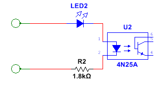
Occasionally, however, we have to deal with using them in a non-complimentary fashion (meaning NPN-to-NPN or PNP-to-PNP, not the grumbling that goes on). Hence this circuit using a 4N25.

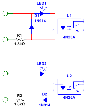
I've made these up without circuit protection, and they work well for their intended purpose. My concern is when Bubba the Maintenance Guy grabs one and wires it in backwards. I've simulated the protection diode in series and in parallel, and they both appear to do the job:

So the question to my long-winded intro: Is there any advantage in using one over the other?
Usually, in an industrial setting, sensors are matched to work with a PLC input module in a complimentary fashion. NPN sensor to a PNP input and vice versa. All at 24VDC. Probably something you already knew.
Occasionally, however, we have to deal with using them in a non-complimentary fashion (meaning NPN-to-NPN or PNP-to-PNP, not the grumbling that goes on). Hence this circuit using a 4N25.

I've made these up without circuit protection, and they work well for their intended purpose. My concern is when Bubba the Maintenance Guy grabs one and wires it in backwards. I've simulated the protection diode in series and in parallel, and they both appear to do the job:

So the question to my long-winded intro: Is there any advantage in using one over the other?


Comments
besides the electronic text book explanations, I can offer this;
The bottom schematic has current limiting capability, and may offer more protection for ground chop.
The top is used alot for RF stuff to clip the chop.
Both are good designs. If Bubba is your main concern, I would pick the bottom schematic. That should give a good
try at stopping the wierd science for happening. In industrial settings, you have devices that may operate outside the
normal parameters learned in books or college. Grounding is a nightmare. A fortress is a good place to be, in that condition.
The second circuit prevents the LED from exceeding the 5V reverse voltage rating
that most of them have.
In practice I can't see the reverse breakdown being an issue if the current is limited
to the reverse leakage of a silicon small signal diode, but the datasheets just
give an abs-max reverse voltage spec, not current.
It's actually a power handling matter mostly (I think), If Imax @ Vfmax = Pmax then the maximum reverse current @ 5V would probably be around a 1/4 of the maximum forward current. But I just hooked up an IR LED in reverse with 330R and wound the supply up to 28V and it didn't breakdown. Did the same with a red LED and it didn't breakdown. Connected them back up in the forward direction and they are fine. No smoke, no fun.
I have used AC optos with back to back bipolar LEDs and external bipolar indicator but also works well when Bubba fixes it too! But I like to rate 24V inputs for 240VAC too, otherwise those sparkies try to send stuff back under warranty "coz it don't work". A single sniff tells you immediately why "it don't work" (no more).