Panel Mount PropPlug Hits The Runway
 idbruce
Posts: 6,197
Hello Everyone
This thread is an extension of another thread, however since this post directly applies to the Propeller chip, I am starting a new thread and I will cross link the two. To find out more about this particular subject, you may want to look this thread over: http://forums.parallax.com/showthread.php/156545-Support-Issue
Without further delay, please allow me to introduce the latest in summer fashion. If there is significant interest, I might be convinced to make a mold for producing these mounts.
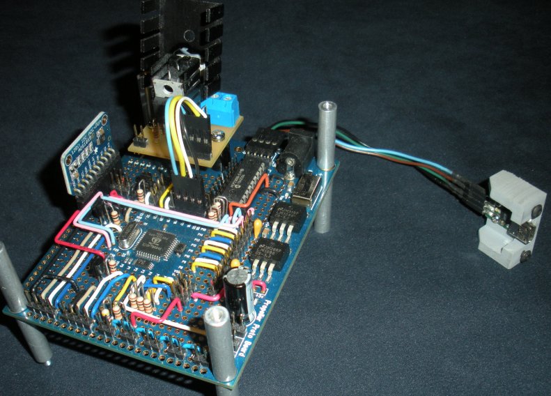
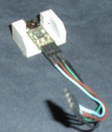
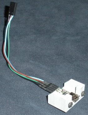
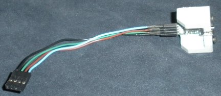
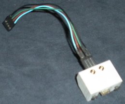
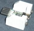
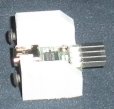


Comments
As for the Panel Mount, that's very clever. I had to come up with something similar for our USB to 232 adapter and here's the end result.
Thanks for the response and thanks for the compliment on the jumper wires. I find it both therapeutic and useful to run my jumpers that way, and perhaps it even boils down to my roots of being an electrician. I have always found it easier to trace neatly run wires, conduit, etc... And when there are a lot of wires, it pays to be neat, so that you can build in layers, while providing easy access to the through holes. Additionally, for some odd reason, I find it comforting to plan and execute colorful wire paths
As for the plug, thanks for that compliment also, but I will have to be much more clever to achieve a panel mount adaptation for the Propeller Memory Card. The readily available microSD card slots are really not all that conducive for panel mounting and I will really have to be creative to make something sturdy. Now I wish I had put a female plug on the Proto Board instead of male pins, then I just could have created a similar plug for a microSD plug (hindsight 20/20).
Your idea was clever as well. There are no problems, only solutions.
Oh and Chris, I could not have achieved the Panel Mount PropPlug without your support and the support of Parallax. Thank you once again for your assistance on this issue.
Bruce
Original Post:
I like it Bruce. I also like Chris' panel mount adapter.
I'm too cheap fugal to embed a Prop Plug with a project.
Here's my attempt at a panel mount Prop Plug receptacle.
My robot remote has two Propeller chips in it. Someone on the forum suggested using female headers and to use long pins to join the connector to the Prop Plug. IMO, it works pretty well.
At the time I was pleased with how it looked. Since then I've tried to follow Ron Czapala's example of making openings in enclosures nice and clean. Now I see the big gabs around the side of the header and think I should have been more patient with the Xacto knife.
One concern about having the Prop Plug permanently connected is the possibility of having reset issue if you have any debug statements in your code. When I have the option, I try to keep the FTDI circuit removable. I've gone so far as to cut the FTDI from a USB version of a Propeller Proto Board.
End of original post.
I decided not to post the above since it didn't included the Prop Plug in the enclosure.
Here's another picture of the remote which shows the slot for the Propeller Memory Card (I think I took the top photo before I had cut the slot for the uSD card).
Unfortunately the uSD card slot on the PMC is so recessed, it's hard to remove the card. It's easier to remove if I add a tab to the uSD card.
Here's a photo of the inside of the "lid" which has the PMC attached to it.
It's not the easiest way to get a panel mount SD card.
Please don't ever hestitate to provide positive input. Your projects will always be welcome in any threads I start and it is always nice to share various ideas, because what may be ideal for one project, may not be ideal for the next, so a variety of solutions in one location is always nice to have.
As for the openings, I like openings to be nice and tight to prevent the entrance of foreign contaminants. (EDIT: With some type of backing to seal the opening)
I suppose it is needless to say that panel mounts are a pain and that the Propeller Memory Card is not going to be a cakewalk, especially for one that makes the card readily accessible. As mentioned in another post that you participated in, I am going to make a special PCB for extending the card slot. In fact, I already purchased the additional card slot for this purpose. I intend to mount this custom PCB to a similar panel mount holder and then the Propeller Memory Card will just slide onto the PCB. Although shown elsewhere in the forum, I am now including an another illustration which should convey my plan.
I never had any problems with the reset issues that I can remember, but I do know that it is a problem, and since you bring it up, it is now a concern.
Are there any known problems with having a PropPlug permanently connected besides the debug statements?
None that I'm aware of. The DEBUG one is just a matter of having the TX line going into the Prop Plug RX line leeching power and powering it up. On power-up (of the FTDI chip) the /RES output will toggle briefly, resetting any connected Propeller chip. The solution of course is to not have the I/O line connected to RX on the Prop Plug set to an output.
That is very good news, because I was getting a little worried, and I was really liking the idea of being able to just run a USB cable to a laptop. It is nice to know that I will be able to program the machine without taking off the enclosure cover.
Out of the source of Sphinx from Michael Park I stole the nice trick to just start the serial driver if RX on the prop is HIGH, thus driven by a powered up PropPlug.
The problem occurs when there is no computer attached to the PropPlug.but the serial driver on the Prop sets TX as output, and HIGH. Now the PropPlug gets power thru the TX line and resets the Propeller.
One other solution I found was to put a PullUp Resistor on TX on the Prop (10K) to keep the PropPlug constantly powered by this stray voltage. Not nice at all but helps.
Next problem is when you attach the USB to the PropPlug. You PC will enumerate the USB devices and while doing so resetting your Prop.
The ONLY reliable solution I found to solve this reset problem is to put a jumper or switch between PropPlug Reset and Prop reset as done for example on the Spinneret.
Enable programming (Reset) or don't. This works always and you can attach and detach your PC at any time without affecting the running software on the Prop. And you can keep all your serial communication running all the time without resets.
just my 2 cents.
Mike
Thanks for your input.
As it stands now, the panel mount PropPlug will be used to program the new machine that I am building, however this machine will be CNC, so there is a chance that it will be connected to a PC or a laptop in the future, and may require a serial driver. In fact, I am fairly certain that I will eventually experiement with a PC.
As I progress through my project, I will report any reset issues that I may have in this thread.
Thanks.
Bruce
Just do it right. Either a jumper or a switch to disable unwanted resets.
You will yell words I would not use in this forum when you connect your USB cable while the CNC is running. Or connect ANOTHER usb-device like a camera or so WHILE connected to your PropPlug on the CNC. Instantly reset thru enumeration of the usb in Windows.
Result: reset of Propeller while running CNC. brilliant.
The ONLY way to get around this is to physically disconnect reset between PropPlug and Propeller unless you WANT to reset/program.
Please include this in your design. Maybe even a pushbutton to be pressed down while applying a firmware update or switch, or jumper. whatever.
Enjoy!
Mike
I love your jumper wire layout as well. It reminds me of the days when people used to take enormous pride in the layout and neatness of the point to point wiring inside their tube radio or transmitter chassis. Even when no one will ever see it.
Many people don't bother anymore and end up with a pile of spaghetti on their board. I think this is a mistake. That neatness and attention to detail is not just a sign of obsessive compulsive behaviour it's important.
Consider that every wire is not just something you throw on there to connect point A to point B. Every wire is a component in your creation as surely as the caps and resistors and even the Propeller itself. Often the wires form the bulk of the finished item!
The placement and routing of every wire deserves as much attention as that of any other component.
In many situations you find out wires really are components. They have resistance, capacitance and inductance. They have current carrying limitations they have voltage break down limitations. They can talk to each other in strange and confusing ways that don't show up on your circuit diagram. Only today I was having trouble with a Propeller resetting itself randomly all the time due to a one foot length of hook up wire hanging off it's reset input and connected to nothing!
At high frequencies, like the edges on the transitions in a digital circuit, your creation is nothing like the circuit diagram you built it from, with simple components connected by conductors. No, it's more like a homogeneous blob of wobbly jelly with every part connected to and interacting with every other part via capacitive or inductive effects. Sometimes more significant than the actual wire you put in there.
And a Bruce says, when your pile of spaghetti is not working or mysteriously playing up you will wish you could see what is what and get in there to fix it!
Thanks for the compliment.
However I must admit, I would be completely lost without a fair amount of neatness. When building machinery, there is always troubleshooting, and tracing wires always takes time, especially if the spaces are cramped. When I first started building the wire bender, I was amazed at how many wires were going back and forth, but at that time, I was building it on an old and large TV console. When I rebuilt the wire bender, to make it more compact and professional looking, I used NEMA 1 enclosures, which I also used for the packaging machine. When using enclosures, you better be neat, or you will never be able to troubleshoot. I will be adding some more pics of both the wire bender and packaging machine enclosures to give you a good indication of what I mean.
These are from the spring bender:
EDIT: I forgot to mention..... See that cover with all those deep switches.... Imagine shoving that into a box of spaghetti..... As it stands, it is one very tight fit. And the same goes for the packaging machine below. I spent a lot of time on the layout, just so these covers would fit with the various cover components.