

Arlo Build

Hey everyone!
This is my post about building the Arlo Platform. During the build, I did not encounter very many problems, and overall, the build went rather smoothly.
Let me know what you think!
Materials:
-2 Caster Wheel Kits (Rev")
-1 Motor Mount and Wheel Kit (Machined Aluminum)
-2 HB-25 Motor Controllers
-1 Loctite 242
-1 Propeller Activity Board
-1 Arlo Power Distribution Board
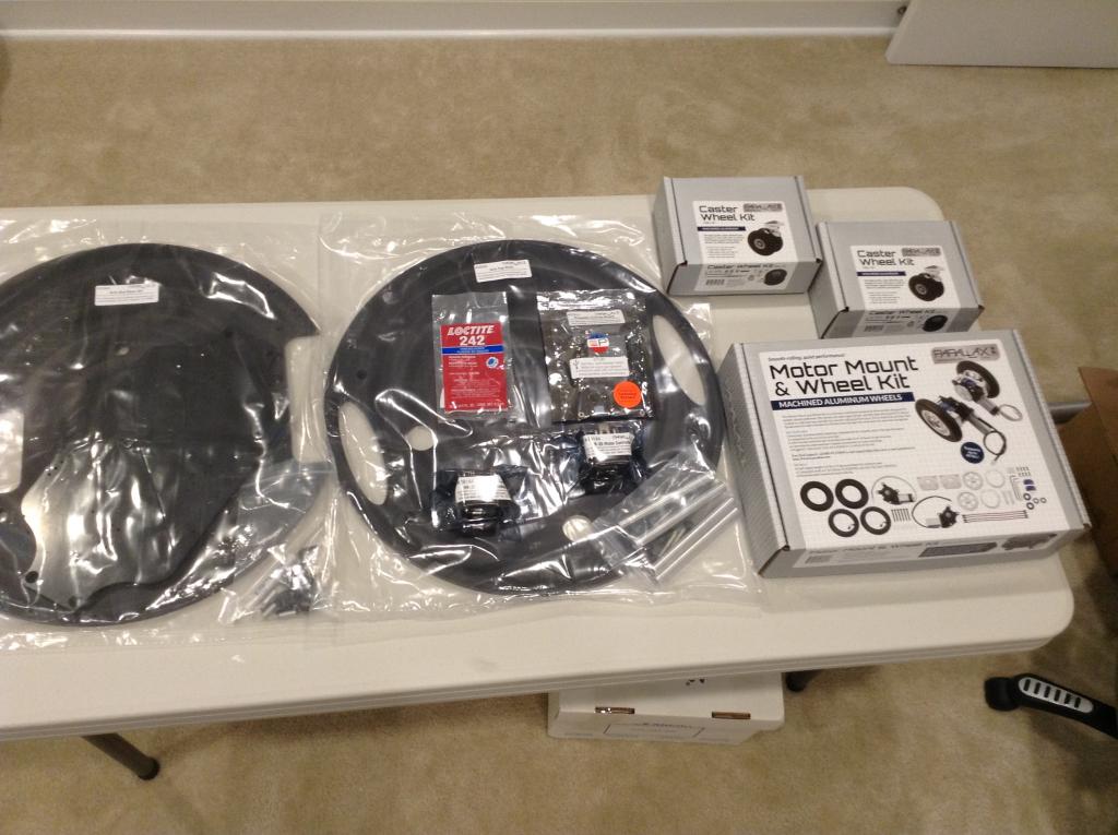
Here is a picture of all of the parts I am using (just the equipment on top of the table):

I am going to start working on the Motor Mount and Wheel Kit first as this is what Mr. Gracey suggested. After that, I am going to work on the Caster Wheel Kits, then the Arlo Bot Base kit, and finally the Arlo top deck.
This is my post about building the Arlo Platform. During the build, I did not encounter very many problems, and overall, the build went rather smoothly.
Let me know what you think!
Materials:
-2 Caster Wheel Kits (Rev
-1 Motor Mount and Wheel Kit (Machined Aluminum)
-2 HB-25 Motor Controllers
-1 Loctite 242
-1 Propeller Activity Board
-1 Arlo Power Distribution Board
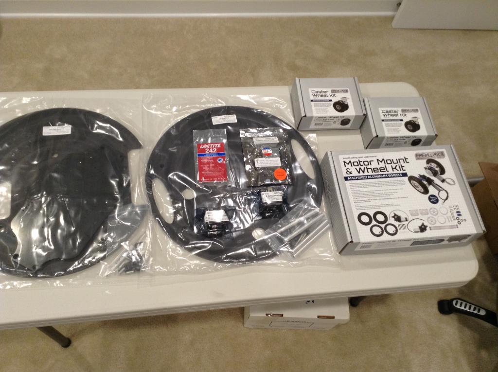
Here is a picture of all of the parts I am using (just the equipment on top of the table):
I am going to start working on the Motor Mount and Wheel Kit first as this is what Mr. Gracey suggested. After that, I am going to work on the Caster Wheel Kits, then the Arlo Bot Base kit, and finally the Arlo top deck.
1024 x 765 - 100K
1024 x 765 - 100K
Comments
Under this there is a picture of the aluminum version of the Motor Mount and Wheel Kit, the one I am using for the build.
These are the parts in the box. Everything looks like it is correctly built, and nothing looks deformed.
Step 1:
One simple thing that would make life a little easier for builders would be if all the guides for building the Arlo was on learn.parallax.com in an Arlo Bot section. This would make it easier and save a little time and some exploring, especially for the people new to the Parallax site. Once I got to the instructions and started step 1, I noticed that one of the axels did not fit into the motor drive shaft. I have attached a picture of the axel, and have pointed to the problem(s).
Eventually, after trying to make the axel fit on all of the positions possible on each motor drive shaft, fruitlessly I may add, I had to hammer the axel in without a wooden block. I was careful and made sure nothing got deformed, so I think it was alright to do that. In addition to not having the wooden block, I had to use more than a few “small taps” to get it in. The other axel was too loose, but luckily, it didn’t matter (I skipped ahead and made sure that the bearing blocks would solve that problem). After fixing that problem, I continued to step 2.
All of the parts in the “encoder kit parts bag” looked right and not deformed.
I put encoder disk on one of the motor drive shafts, and the encoder disk fit very well. The other encoder disk was not made correctly, and it turned out that it had some extra plastic that was not cut off of the edges. I had to use an exacto knife to cut the extra plastic out. It is fine now that I cut the extra plastic out, but it was a problem that could have caused serious malfunction to the encoders if not dealt with.
Step 3:
I have attached the final product as of the end of step 3, and so far, I have not encountered any problems that I can’t easily fix. The documentation was well written for the bearing, and I had no problems installing the bearings.
Step 4:
I have included a picture of the bearing blocks that are required in step 4 of the guide, and they seem to look just how they are supposed to look.
Completing step 4 was pretty easy, and the instructions were well documented in the guide Parallax provides. I had no trouble getting the bearing blocks in place, and it has continued to stays tight on the bearing.
Step 5:
Step 5 was well documented, but the image of the drive pin was a little distorted and I would prefer to have something that clearly shows what the drive pin is. This is the image of the piece of “equipment” that I used.
The drive pins did not easily fit into the axel, and I had to hammer them in hard. I do realize though, that hard for me might not actually be that hard for experienced builders, as I have almost no building experienceJ. Other than that, everything went according to plan.
Step 6:
As I moved on to step 6, I inspected the screws and the standoffs and nothing seemed deformed or bent. I have included a picture of them from top view angle.
The screws went in seamlessly, and I did not have a problem with them. The instructions were well documented, as usual, and did not seem to have any flaws in them. I have included a picture of the two motor drive shafts as of the end of this step.
The last steps were very easy, and were well documented. I have included a picture of the final result.
In the end, I really only had a one serious problem, which was that one encoder had some extra plastic on its outside which could have caused a malfunction. Other than that, this part of the build was not that challenging to complete, and was well developed.
Building the Caster Wheel Kits:
Below, I have included a picture of the parts that come in the Caster Wheel Kits. A great thing that Parallax did was include the setup guide in the Caster Wheel Kit box.
Step 1 + 2:
Steps 1 & 2 were very easy to complete and were well documented in the assembly guide. I have included a picture of the Caster wheel as of the end of step 2.
Step 3 + 4 + 5:
Step 3 was easy and, as usual, well documented. During step 4, I used Loctite to get improved results, as the Loctite helped keep the swivel rod in place. I let the Loctite sit for over a day, to make sure it would dry. Step 5 was very easy and well documented, just like steps 3 and 4. Below is a picture of the build as of the end of step 5.
I repeated the same process to complete the other Caster Wheel Kit, and have included a picture of the two of them next to each other.
Building the Arlo Base Kit:
I have included the picture of the bottom deck and what it comes with.
Step 1:
During step 1, I didn’t encounter any problems other than a little confusion in the instructions. In the guide, Parallax did not specify which kit the screws that were needed came from, so I got a little confused. Eventually, after I scratched my head for a few minutes, I figured out the screws were in the Caster Wheel Kit (yes, I know it was a pretty dumb mistake to makeJ). I have included a picture of the Caster wheels mounted on the Arlo base deck.
Step 2:
Step 2 was easy to complete and well documented in the guide Parallax provides on their website. I had no trouble installing the motors on the base deck, and have included a picture of the final product after step 2.
Step 3:
I skipped step 3 because I don’t have any batteries, but the instructions seemed designed well, and I have all of the parts - none of which are deformed - to install the batteries.
Step 4:
Step 4 was also very easy and well documented in the guide. I didn’t have any problems with installing the battery tray, and the instructions in the guide were clear. Below is a picture of the underside of my Arlo.
Step 1:
Step 1 of building the Arlo top deck was very simple and easy to complete. It was explained well in the guide, and the parts fit seamlessly. I have included a picture of the standoffs.
Step 2:
Step 2 was, as usual, very easy and well designed.
Overall, building the hardware for the Arlo was a good, fun experience that didn’t have very many problems. I have included a picture below of the final product. I do still have to add sensors, the ActivityBoard, batteries, and HB-25 motor controllers, but the frame is built and ready to be “hacked”J.
Currently, I just have to add the brains and accessories to complete my build. Stay tuned for the rest!!!
Ken Gracey