

1kW servo controller
 ManAtWork
Posts: 2,369
ManAtWork
Posts: 2,369
When the word "servo" is used together with the propeller we usually think of a small box with a tiny motor and gear used for model crafting or (toy) robots. When I say "servo" I mean something completely different. This is my latest project, a servo controller targeted for use in industrial CNC machines. It runs from 230V AC mains voltage and can deliver up to 6A or aprox. 1kW. Currently, brushed or brushless permanent magnet motors with resolver or absolute encoder feedback are supported.
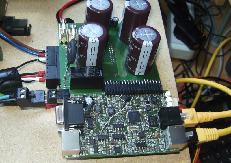
In the front you can see the actual controller board with the propeller. The RJ45 sockets on the right are for the command and feedback input (encoder). The socket on the left is for the (optional) resolver and the SUBD connector for auxiliary IO. The board in the rear is the power stage. On top there are capacitors, a relay (soft start) and fuses. The IGBTs, the heatsink and the optoisolators are mounted on the bottom side.
Here is a video with the test run of a small brushless motor (330W): http://youtu.be/2ELWWXflVbA

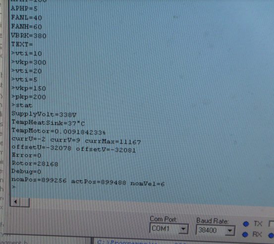
Parameters can be adjusted with the serial terminal. The status display shows a rectified voltage of 338V.
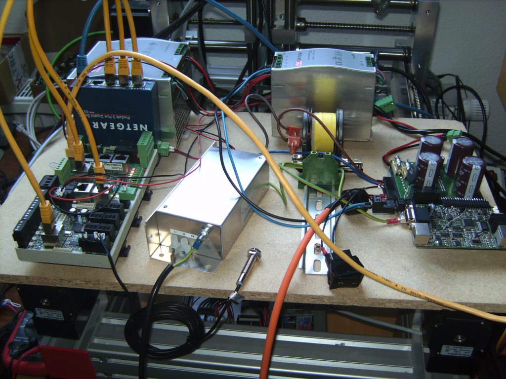
In the video you can also see my CNC software running on a PC. But the PC is used only as GUI. The actual real time stuff is, of course;), done by another propeller. It is located on the board in front of the "netgear" (ethernet switch) on the left. It receives it's data from the PC and generates step/dir pulses for the servo. The metallic box is the (mandatory) power line EMI filter.
In the front you can see the actual controller board with the propeller. The RJ45 sockets on the right are for the command and feedback input (encoder). The socket on the left is for the (optional) resolver and the SUBD connector for auxiliary IO. The board in the rear is the power stage. On top there are capacitors, a relay (soft start) and fuses. The IGBTs, the heatsink and the optoisolators are mounted on the bottom side.
Here is a video with the test run of a small brushless motor (330W): http://youtu.be/2ELWWXflVbA
Parameters can be adjusted with the serial terminal. The status display shows a rectified voltage of 338V.
In the video you can also see my CNC software running on a PC. But the PC is used only as GUI. The actual real time stuff is, of course;), done by another propeller. It is located on the board in front of the "netgear" (ethernet switch) on the left. It receives it's data from the PC and generates step/dir pulses for the servo. The metallic box is the (mandatory) power line EMI filter.

1024 x 768 - 163K

800 x 564 - 106K
553 x 492 - 43K
Comments
No support for incremental encoders?
What absolute encoder technology are we talking?
When will this be commercially available?
nice work. What's the maximum inputfrequency of the feedback-input?
best regards
Stefan
With brushless motors absolute encoders are much easier to handle because you always know the direction of the rotor field vector. Furthermore, all abs encoders I know have a resolution equal to a power of two (14, 16 or 17 bits), so with 4 or 8-pole motors you only need shifts and the sine lookup table.
Currently two different encoders are supported, Sanyo Denki R2-series and my own homebuild ones. The Sanyo encoders communicate over an RS485 line and use a very odd 18-bit frame format. Without a propeller it would surely take an FPGA to implement. Thanks to the propeller I could theoretically support any serial protocol. Unfortunatelly, the standard ones like EnDat or BISS are a bit complicated and I haven't got the time, yet.
The maximum count rate for incremental encoders and the step/dir input is around 1MHz. This limits the resolution to 5000cpr @ 3000RPM. Absolute encoders can have a higher resolution. You then need to use a pulse multiplying factor so that the step signal can keep up. This way you don't have the full resolution for positioning but the higher encoder resolution helps the velocity control loop to run smoother at higher gains.
Induction motors: This would also be possible. It just doesn't make much sense, economically. You can buy complete VFDs for the same money, at least for standard applications up to 400Hz. However, drives for high frequency spindles with 1000Hz or more are difficult to find and hard to tune. You don't want to pay the western drives and the chinese ones have so bad manuals nobody understands how to set up the parameters. So as soon as I need a HF spindle (or a customer pays me for it) I will also build in support for induction motors.
I hope that I can sell the servo controller before the end of the year. The biggest problem is that you can't expect the user to type numbers into the serial terminal. Most of us here are used to it but for a commercial product there has to be a nice looking GUI program to setup evrything. This is relatively easy if only a set of "known good motors" are supported. Then you only need to pick one from a list and adjust the gain to the load. If I wanted to sell it as "universal" drive for any kind of motor there has to be some auto tuning feature. Most people aren't able to tune a PID loop manually.
For what purpose? Standard (50/60Hz) induction motors are not very well suited for servo applications. To limit the startup current with direct switching they have a higher than necessary air gap and rotor winding resistance and that results in a lower than necessary efficiency and stall torque. The missing permanent magnets also mean that you must drive a permanent "standby" current through the windings to sustain the rotor field, at least if you want fast response. The steady current heats up the motor as known from stepper motors.
There are induction motors that are optimized for VFD or servo applications but they are more expensive than permanent magnet BLDC motors. You can convert almost any cheap chinese BLDC motor to a servo by adding an encoder. You'd only save money if the induction motor needs to be so big that the price of the (otherwise required) magnets is significant. So IMHO this only makes sense for very big motors. Even then I doubt it because there usually are plenty of damaged industrial robots you can salvage big servo motors from at your local scrap dealer.
A advantage of induction motors would be that you don't have to know the rotor position at startup so you don't need an absolute encoder. I try to avoid that problem by clever software that can "guess" the rotor position even with only an incremental encoder (for existing motors) or by offering a cheap absolute encoder I build myself (for new motors).
2) Traction motors?
3) Torque limit control / stall detection
4) Some application you haven't though of, but a potential customer has?
If rare earth magnets become more expensive induction motors will be used for more roles,