

My Activity Bot build

Just thought it might be fun to post my progress as I put this little guy together and (hopefully  ) get him up and running...
The first thing to do was to set up a work area. They drill us at work about the hazards of ESD (Electro-Static Discharge) events and their potentially devastating effect on exposed circuitry. So I decided to buy an ESD workmat and wrist strap for my work area. Also had to dig around and locate all my tools again. Now I'm ready to begin assembly!!!

The first thing to do was to set up a work area. They drill us at work about the hazards of ESD (Electro-Static Discharge) events and their potentially devastating effect on exposed circuitry. So I decided to buy an ESD workmat and wrist strap for my work area. Also had to dig around and locate all my tools again. Now I'm ready to begin assembly!!!
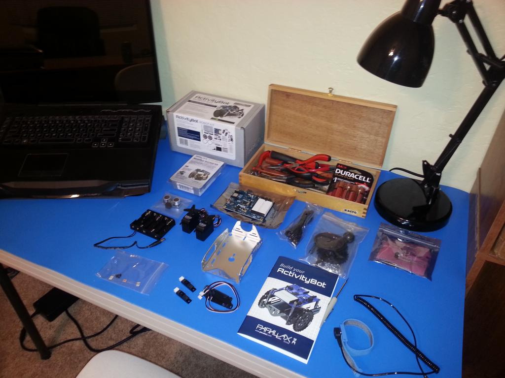
1024 x 768 - 91K
Comments
So far I'm VERY impressed at how well this is going together. My only comment would be some of the odd angles chosen for some of the step illustrations. Step 3 for example might be clearer if the view was pitched a little toward the viewer. Step 7 is a similarly odd angle choice, but hey if that's the only thing I can fault, then this is a pretty impressively engineered kit. Kudos to Parallax!
Well that's all for tonight. I will finish up the mechanical assembly in the next go around...hopefully tomorrow.
ESD huh? I put mine together on the carpeted living room floor while the kids played with Legos around me . . . looking back I can see why that wasn't the best idea, but we had fun.
And that's all that really counts!
This is what I came up with:
It's going to have a little bit more grip at the back end than the ball would, so we'll have to see if that impedes pivoting. If it does, I can always swap it out for the original part.
I like the look better though...
using a caster wheel for very long...
Your current Tail Wheel set up, will most definitely cause skidding problems during a 'turn in place' scenario, the stickiness of the rubber will likely cause your bots
tail end to hop as it makes the sharp turn..
But not to worry, adding the Rudder Steering System will fix all that, and more...:)
-Tommy
One thing though: your workbench is WAY too tidy. You're making the rest of us look bad. PM me your address and I'll snailmail you a bunch of wire clippings, stripped insulation and solder blobs to sprinkle about. And for Pete's sake, make a few burn marks on your desktop with a soldering iron.
Please.
They have wheels that can slide sideways that look good too, I can't seem to remember the name. It's like a mechanum wheel but passive.
As I can see you've been told already, the hard plastic allows it to slide during rotation without causing friction. Ideally the trailing wheel would roll in every direction but that isn't easy to do. Holonomic wheels are expensive and finicky and casters have a tendency to lock up and drag at odd angles on light robots. A hard plastic ball is able to drag easily and instantly in almost any direction.
But don't let us discourage you from trying and learning!
P.S. I'll try to remember to post a picture of the amazing trailing wheel I came up with for my Lego Mindstorm robot. It took months of experimentation to come up with!
Sounds like a must-see, clofland! Can't wait.
A favorite of mine, is this set-up, and has been the base for several different variations.
I think a crafty person would be able to shape material (3D printer?,WoodShop?,Playdough?) into a Rudder Steering System Assembly and fasten onto the Activity Bot,
Thus, making the Ultra Ultimate Activity Bot Rudder Steering System Assembly,. I think it would be a good system...:thumb:
-Tommy
Probably too large though
http://www.robotmesh.com/2-75-omni-directional-wheel-double-roller-2-pack?gclid=Cj0KEQjwopOeBRC1ndXgnuvx8JYBEiQAq4RPt5TJOJ0zYK2YY75AMKLKEZE6NXB_gjLJFWAkvSNrGHoaAr7t8P8HAQ
After building several dozen different Lego casters, this is the one I finally came up with that works beautifully:
Ace Hardware!
I actually tried a few store bought casters and this one worked really well because it is close to a ball. The more tire shaped ones still had a hard time changing direction rapidly enough to not affect the robot's navigation. This one is able to pivot at a very fine point, so it almost never drags the robot off course in direction changes.
Oh, and here a is a front view in case you wonder what he looks like:
I could go into more detail, but maybe that should be on my thread, not someone else's.
When I bought my Activity Bot, I had seen video of the Boe Bot wandering around with the Ping))) Sensor swiveling back and forth on this bracket assembly and knew right away I wanted to mod my Activity Bot to do the same. It was a fairly easy mod but it did require me to remove the activity board, which in turn required me to remove the front 2 screws on each of the drive servos. Here are some pics of that effort:
Here is a picture of the "power up" test: