

32x 16 RGB Message Board
 tomcrawford
Posts: 1,129
tomcrawford
Posts: 1,129
32 Column by 16 Row RGB Message Board
Introduction
I have done a number of LED message boards, both monochrome and bi-color (Red, Green, and Yellow or Orange). I have wanted to do RGB, but couldnt find RGB panels. I finally decided to build my own. Here is a pointer to the result.
http://youtu.be/qnhe3_DlHa4
Selecting the Module
I wanted a 32 x 16 panel and just couldnt see putting 192 individual RGB LEDs on a board; 8 by 8 modules seemed reasonable. I would have liked to use common cathode modules along with Holteck HT1632C drivers, but common cathode RGB modules really seem to be made out of unobtainium. The only place I could find that claims to sell them in Futurelek, and they dont actually have any (despite what they claim) (as of spring and summer 2014).
Common anode modules are readily available and because of RainbowDurino will likely continue to be. Currently they are going for $4 5 in fives and tens. I have eight on a panel, arranged four across and two high.
Driving the Modules
So there are 32 pins on an 8 x 8 modules, eight anodes and 24 (three times eight) cathodes. I multiplex by turning on one anode pin and enabling the appropriate cathode pins, slight delay and then go on to next anode.
Each anode pin has to source current for as many as 24 LEDs and has to turn on and off fairly quickly. I chose the Mitsubishi M54564P 8-unit 500mA Source Type Darlington Transistor Array. Each of these drives two 8 x 8 modules.
For column sinks I selected TI TLC5916 8-channel Constant-current LED Sink Drivers. Each module has three of these, one each for the RED, GREEN, and BLUE cathode pins. The current for each device (that is to say each color of each module) is programmable. That means no current limiting resistors and also means you can program the intensity on a module basis.
Driving the Drivers
Of course, this is ParallaxPropellorPowered. All eight cogs are used, some more than others. The main cog mostly just lights off the others and is then available for setting current levels. Cog 1 runs Parallax Serial Terminal. Of the other six, one is a host interface, one provides timing, and the other four are used to load data into the cathode drivers.
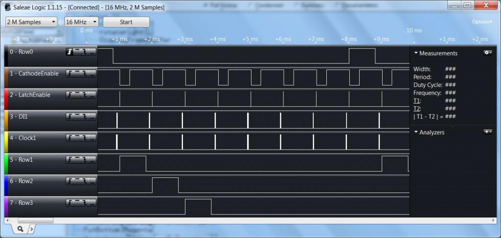
The first timing diagram shows an entire frame. The top trace is ROW0 enable, then cathode enable (active low), cathode data latch, cathode data and clock, and then ROW1, ROW2, and ROW3.
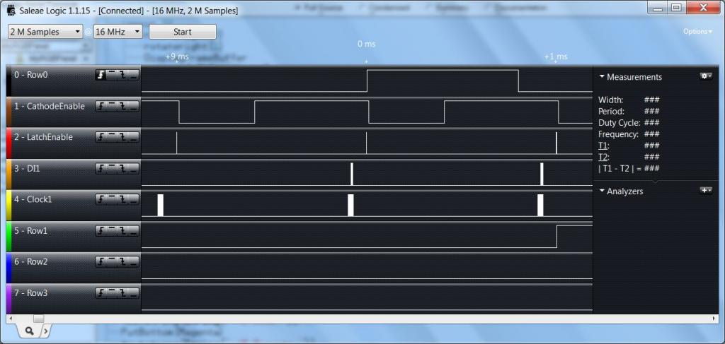
The next timing diagram zooms in on a single scan line. The cathode data are clocked into the TLC5916s, and then latched into the drivers. Next, the anode driver is enabled and then the cathodes are enabled. The brightness is controlled by modulating the Cathode Enables. The cathodes are turned off, the anode is turned off and so on to the next scan line.
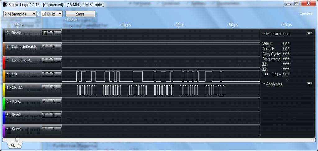
The final timing diagram shows data being loaded into one set of cathode drivers. There are six sets of eight clocks each; enough to load two modules, three colors each.
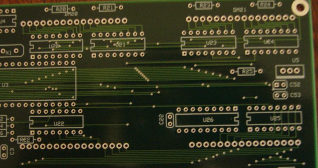
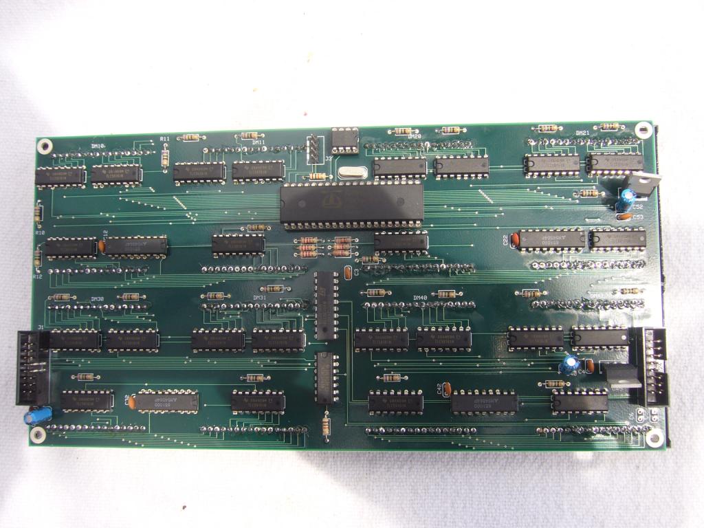
Here is a picture of the panel. ICs are on one side, modules on the other. The other picture shows one quad (two modules) of an unpopulated panel.
Introduction
I have done a number of LED message boards, both monochrome and bi-color (Red, Green, and Yellow or Orange). I have wanted to do RGB, but couldnt find RGB panels. I finally decided to build my own. Here is a pointer to the result.
http://youtu.be/qnhe3_DlHa4
Selecting the Module
I wanted a 32 x 16 panel and just couldnt see putting 192 individual RGB LEDs on a board; 8 by 8 modules seemed reasonable. I would have liked to use common cathode modules along with Holteck HT1632C drivers, but common cathode RGB modules really seem to be made out of unobtainium. The only place I could find that claims to sell them in Futurelek, and they dont actually have any (despite what they claim) (as of spring and summer 2014).
Common anode modules are readily available and because of RainbowDurino will likely continue to be. Currently they are going for $4 5 in fives and tens. I have eight on a panel, arranged four across and two high.
Driving the Modules
So there are 32 pins on an 8 x 8 modules, eight anodes and 24 (three times eight) cathodes. I multiplex by turning on one anode pin and enabling the appropriate cathode pins, slight delay and then go on to next anode.
Each anode pin has to source current for as many as 24 LEDs and has to turn on and off fairly quickly. I chose the Mitsubishi M54564P 8-unit 500mA Source Type Darlington Transistor Array. Each of these drives two 8 x 8 modules.
For column sinks I selected TI TLC5916 8-channel Constant-current LED Sink Drivers. Each module has three of these, one each for the RED, GREEN, and BLUE cathode pins. The current for each device (that is to say each color of each module) is programmable. That means no current limiting resistors and also means you can program the intensity on a module basis.
Driving the Drivers
Of course, this is ParallaxPropellorPowered. All eight cogs are used, some more than others. The main cog mostly just lights off the others and is then available for setting current levels. Cog 1 runs Parallax Serial Terminal. Of the other six, one is a host interface, one provides timing, and the other four are used to load data into the cathode drivers.
The first timing diagram shows an entire frame. The top trace is ROW0 enable, then cathode enable (active low), cathode data latch, cathode data and clock, and then ROW1, ROW2, and ROW3.
The next timing diagram zooms in on a single scan line. The cathode data are clocked into the TLC5916s, and then latched into the drivers. Next, the anode driver is enabled and then the cathodes are enabled. The brightness is controlled by modulating the Cathode Enables. The cathodes are turned off, the anode is turned off and so on to the next scan line.
The final timing diagram shows data being loaded into one set of cathode drivers. There are six sets of eight clocks each; enough to load two modules, three colors each.
Here is a picture of the panel. ICs are on one side, modules on the other. The other picture shows one quad (two modules) of an unpopulated panel.
1024 x 487 - 71K
1024 x 487 - 67K
1024 x 487 - 71K
1024 x 544 - 78K
1024 x 768 - 117K
Comments
would leave embarassing large empty spaces!
If I had planned to go into production and pay to have the boards assembled, yeah. But I'll only assemble a few for my own use.
https://www.youtube.com/watch?v=ZBD5Gi7Sm4I