

MAX1497 ADC and Propeller Quick Start
 CelticLord
Posts: 50
CelticLord
Posts: 50
Anyone out there who can help me with this setup? I am exausted trying.
Data Sheet ... http://datasheet.electronicafacil.net/MAXIM/MAX1497.pdf
The code seems to be alright I think......
Data Sheet ... http://datasheet.electronicafacil.net/MAXIM/MAX1497.pdf
The code seems to be alright I think......
CON
  _clkmode = xtal1 + pll16x                                  'Standard clock mode * crystal frequency = 80 MHz
  _xinfreq = 5_000_000

  CS = 11                                                    ' Chip Select
  Clk = 9                                                    ' Clock
  DOut = 8                                                   ' DataOut
  DIn = 10                                                   ' DataIn
  Cnts2Mv = $001F

OBJ
  pst    : "Parallax Serial Terminal Plus"
  BS2    : "BS2_Functions"                                   ' Create BS2 Object
VAR
  Long wresult1, wresult2, wValue                                               ' Conversion Result
  Word Volts                                                 ' Result --> mVolts
  Word Value                                                 ' Result --> Value
  Byte Status, rFlag
PUB Main
  pst.Str(String(2,1,1,"ADC CH 0: ",2,1,2,"        Raw   : Volts"))
  dira[CS]~~
  outa[CS]~~
  outa[CS]~                                                  ' Enable ADC

  BS2.SHIFTOUT (DIn, CLK, BS2#MSBFIRST, 8, 130)              ' Enable Write to Control Register %10 00001 0
  BS2.SHIFTOUT (DIn, CLK, BS2#MSBFIRST, 16, 24576)            ' Enable bit ON ,RANGE = 2.0 Volts %0110000000000000

  repeat
    MAX1497

PRI MAX1497
  'outa[CS]~                                                  ' Enable ADC

  Status := 8
  repeat while Status == 8
    BS2.SHIFTOUT (DIn, Clk, BS2#MSBFIRST, 8, 192)            ' Command Read Status Register 100000000
    Status := BS2.SHIFTIN (DOut, Clk, BS2#MSBPOST, 8)        '^
    rFlag := (Status & %00001000)                            '|
    pst.Str(String(2,12,9,"Not Ready"))                      '|
    waitcnt(clkfreq+cnt)                                     '|
                                                             '└── Repeat untill Status 0(Data valid in ADC Result)

  BS2.SHIFTOUT (DIn, Clk, BS2#MSBFIRST, 8, 208)              ' Enable READ ADC Result Register 1 (12 MSBs) %11010000
  wresult1 := BS2.SHIFTIN (DOut, Clk, BS2#MSBPOST, 12)
  BS2.SHIFTOUT (DIn, Clk, BS2#MSBFIRST, 8, 232)              ' Enable READ ADC Result Register 2 ( 8 LSBs) %11101000
  wresult2 := BS2.SHIFTIN (DOut, Clk, BS2#MSBPOST, 8)
  pst.Str(String(2,12,9,"  READY  "))
  'outa[CS]~~                                                 ' Disable ADC

  wValue := (wresult1 << 8) + wresult2                        'Combine Result 12 Bit REG A + 8 Bit REG B

  Volts := wresult1 / Cnts2Mv
  pst.Str(String(" ",2,7,3))
  pst.dec(wValue)
  pst.Str(String(" ",2,18,3))
  pst.dec(Volts)
PLEASE anyone who can help PLEASE 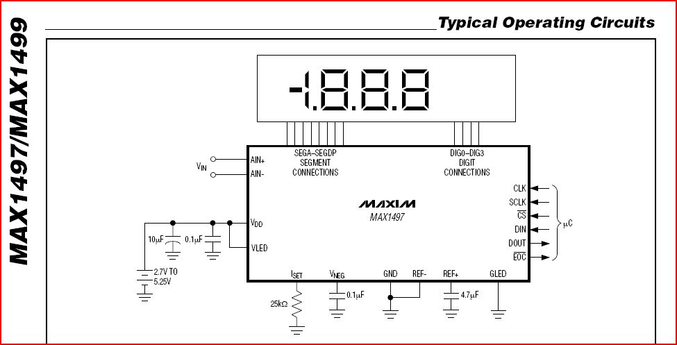
975 x 497 - 64K
Comments
I notice you set the chip select (CS) line low but as the code is now, it was never high. Most SPI deices need the CS line to transition from high to low in order to enable the chip.
When you say "the code seems to be alright", why do think so? Did you write if yourself of did you get it from someone who said it works?
A photo of your setup may also be a good idea.