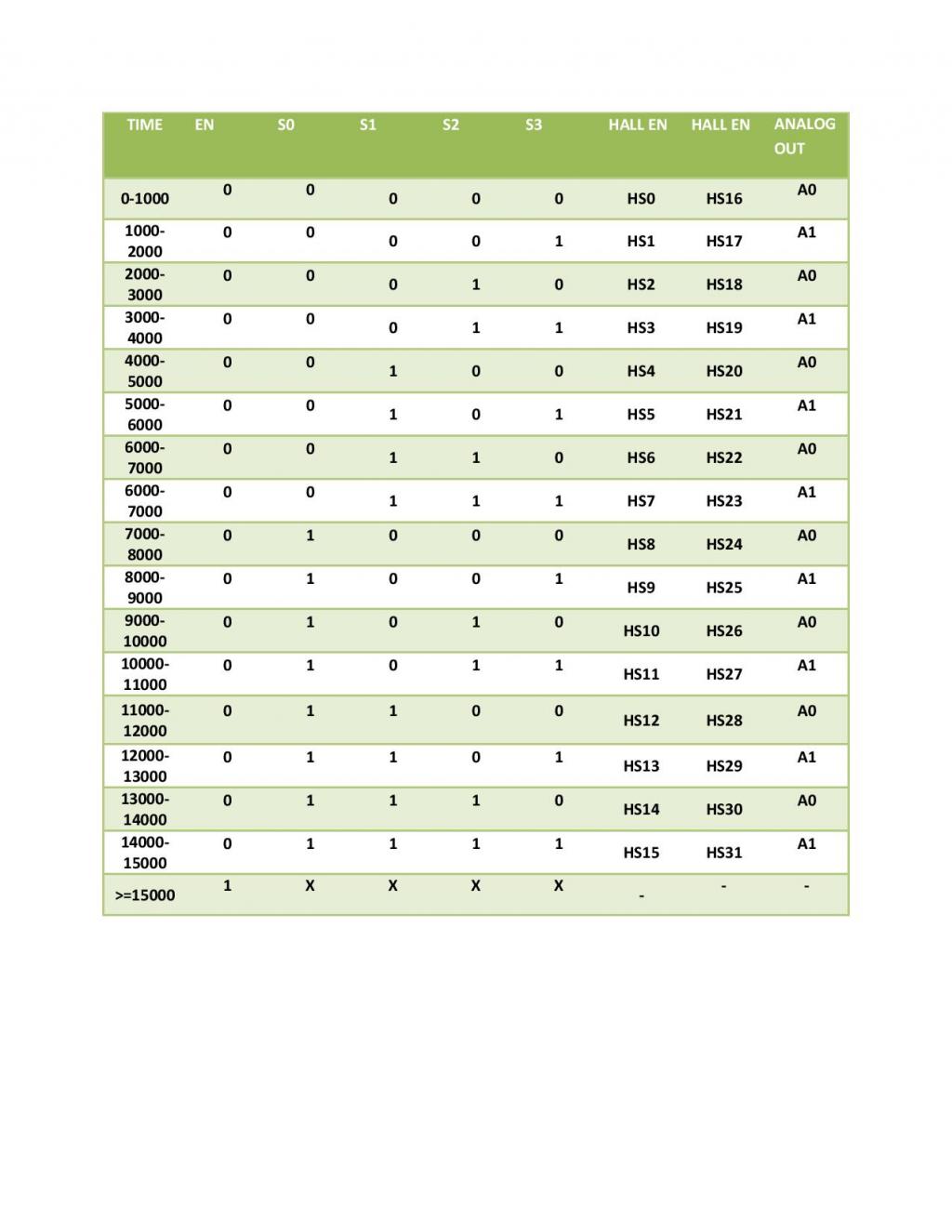
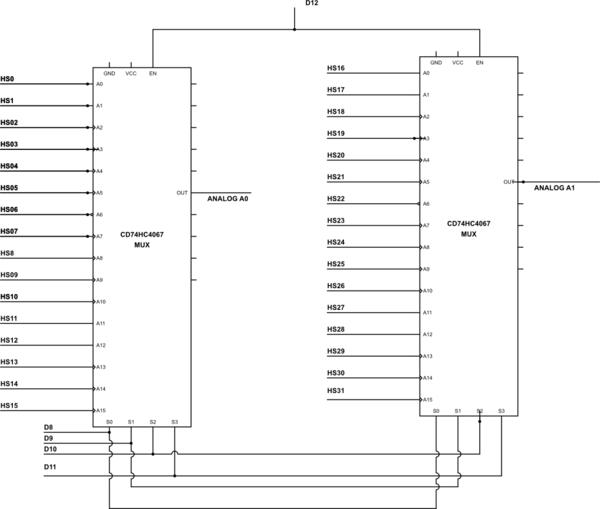
truth table Implimentation using C
Dear all,
I need some idea on implementing above truth table on arduino platform or in C. In above truth table s0,s1,s2,s3, En are my input Depend on State of input my Output changes.
SO entry condition for my program will be time and another is Input from table . So can some one suggest me Hw can do this.
I need some idea on implementing above truth table on arduino platform or in C. In above truth table s0,s1,s2,s3, En are my input Depend on State of input my Output changes.
SO entry condition for my program will be time and another is Input from table . So can some one suggest me Hw can do this.


Comments
So plain C code is also fine?
Could you clarify the truth table al little bit more?
Does the 0 - 1000 mean, from 0 until 1000 (including 1000) or from 0 till 1000 (excluding 1000)?
You say that the EN, S0-S3 are inputs but I don't see how the time influences the output.
Also this is not the Arduino forum.
[COLOR=#000000][FONT=monospace]int sensorArray[32] ;[/FONT][/COLOR] [COLOR=#000000][FONT=monospace]int selectPinZero = 8;[/FONT][/COLOR] [COLOR=#000000][FONT=monospace]int selectPinOne = 9;[/FONT][/COLOR] [COLOR=#000000][FONT=monospace]int selectPinTwo = 10;[/FONT][/COLOR] [COLOR=#000000][FONT=monospace]int selectpinthree=11;[/FONT][/COLOR] [COLOR=#000000][FONT=monospace]int inputPinOne = 0;[/FONT][/COLOR] [COLOR=#000000][FONT=monospace]int inputPinTwo = 1;[/FONT][/COLOR] [COLOR=#000000][FONT=monospace]static float ARDUINO_ANALOG_SCALING = 0.00488758;[/FONT][/COLOR] [COLOR=#000000][FONT=monospace]int sensor1;[/FONT][/COLOR] [COLOR=#000000][FONT=monospace]int sensor2;[/FONT][/COLOR] [COLOR=#000000][FONT=monospace]int voltage1;[/FONT][/COLOR] [COLOR=#000000][FONT=monospace]int voltage2;[/FONT][/COLOR] [COLOR=#000000][FONT=monospace]int Current_Sensor1;[/FONT][/COLOR] [COLOR=#000000][FONT=monospace]int Current_Sensor2;[/FONT][/COLOR] [COLOR=#000000][FONT=monospace]int array[17][5]={[/FONT][/COLOR] [COLOR=#000000][FONT=monospace] {0,0,0,0,0},[/FONT][/COLOR] [COLOR=#000000][FONT=monospace] {0,0,0,0,1},[/FONT][/COLOR] [COLOR=#000000][FONT=monospace] {0,0,0,1,0}, [/FONT][/COLOR] [COLOR=#000000][FONT=monospace] {0,0,0,1,1},[/FONT][/COLOR] [COLOR=#000000][FONT=monospace] {0,0,1,0,0},[/FONT][/COLOR] [COLOR=#000000][FONT=monospace] {0,0,1,0,1},[/FONT][/COLOR] [COLOR=#000000][FONT=monospace] {0,0,1,1,0},[/FONT][/COLOR] [COLOR=#000000][FONT=monospace] {0,0,1,1,1},[/FONT][/COLOR] [COLOR=#000000][FONT=monospace] {0,1,0,0,0},[/FONT][/COLOR] [COLOR=#000000][FONT=monospace] {0,1,0,0,1 },[/FONT][/COLOR] [COLOR=#000000][FONT=monospace] {0,1,0,1,0},[/FONT][/COLOR] [COLOR=#000000][FONT=monospace] {0,1,0,1,1},[/FONT][/COLOR] [COLOR=#000000][FONT=monospace] {0,1,1,0,0 },[/FONT][/COLOR] [COLOR=#000000][FONT=monospace] {0,1,1,0,1},[/FONT][/COLOR] [COLOR=#000000][FONT=monospace] {0,1,1,1,0 },[/FONT][/COLOR] [COLOR=#000000][FONT=monospace] {0,1,1,1,1}, [/FONT][/COLOR] [COLOR=#000000][FONT=monospace] {1,0,0,0,0} [/FONT][/COLOR] [COLOR=#000000][FONT=monospace] };[/FONT][/COLOR] [COLOR=#000000][FONT=monospace]void setup(){[/FONT][/COLOR] [COLOR=#000000][FONT=monospace] pinMode(selectPinZero, OUTPUT);[/FONT][/COLOR] [COLOR=#000000][FONT=monospace] pinMode(selectPinOne, OUTPUT);[/FONT][/COLOR] [COLOR=#000000][FONT=monospace] pinMode(selectPinTwo, OUTPUT);[/FONT][/COLOR] [COLOR=#000000][FONT=monospace] pinMode(selectpinthree,OUTPUT);[/FONT][/COLOR] [COLOR=#000000][FONT=monospace] pinMode(inputPinOne, INPUT);[/FONT][/COLOR] [COLOR=#000000][FONT=monospace] pinMode(inputPinTwo, INPUT);[/FONT][/COLOR] [COLOR=#000000][FONT=monospace]}[/FONT][/COLOR] [COLOR=#000000][FONT=monospace] void loop()[/FONT][/COLOR] [COLOR=#000000][FONT=monospace]{[/FONT][/COLOR] [COLOR=#000000][FONT=monospace] for(row=0;row<17;row++)[/FONT][/COLOR] [COLOR=#000000][FONT=monospace] {[/FONT][/COLOR] [COLOR=#000000][FONT=monospace] for(column=0;column<5;column++);[/FONT][/COLOR] [COLOR=#000000][FONT=monospace] {[/FONT][/COLOR] [COLOR=#000000][FONT=monospace] digitalWrite(Enablepin,array[row][column]);[/FONT][/COLOR] [COLOR=#000000][FONT=monospace] digitalWrite(selectPinZero,array[row][column+1]);[/FONT][/COLOR] [COLOR=#000000][FONT=monospace] digitalWrite(selectPinOne,array[row][column+2]);[/FONT][/COLOR] [COLOR=#000000][FONT=monospace] digitalWrite(selectPinTwo,array[row][column+3]); [/FONT][/COLOR] [COLOR=#000000][FONT=monospace] digitalWrite(selectpinthree,array[row][column+4]); [/FONT][/COLOR] [COLOR=#000000][FONT=monospace] sensor1=analogRead(inputPinOne);[/FONT][/COLOR] [COLOR=#000000][FONT=monospace] sensor2=analogRead(inputPinTwo);[/FONT][/COLOR] [COLOR=#000000][FONT=monospace] voltage1=sensor1 * ARDUINO_ANALOG_SCALING;[/FONT][/COLOR] [COLOR=#000000][FONT=monospace] voltage2=sensor2* ARDUINO_ANALOG_SCALING;[/FONT][/COLOR] [COLOR=#000000][FONT=monospace] Current_Sensor1=(10*voltage1)-25;[/FONT][/COLOR] [COLOR=#000000][FONT=monospace] Current_Sensor2=(10*voltage2)-25;[/FONT][/COLOR] [COLOR=#000000][FONT=monospace] }[/FONT][/COLOR] [COLOR=#000000][FONT=monospace] }[/FONT][/COLOR] [COLOR=#000000][FONT=monospace]}[/FONT][/COLOR]Maybe this? http://tronixstuff.com/2013/08/05/part-review-74hc4067-16-channel-analog-multiplexerdemultiplexer/
What are you trying to do exactly?
You mentioned a time frame. Do you want to record the samples periodically?
Considering that the last line in the table is >= 15000, I'd be willing to say the upper limits are excluded.
@Ajit,
The math should be pretty straightforward. If you take the time value divided by 1000 that should give you 0-15 (IIRC, integer division is truncated, isn't it?) to use in your array
The code you posted looks to loop through all 16 channels and read the analod value on each. Given the truth table, I'm not certain that is what you are wanting to do.