Propeller USB dongle. First design
 TC
Posts: 1,019
Hello all,
For some time, I wanted to have a way to have a propeller with me all the time so I could try out code ideas, or to learn something new. So I came up with the idea of making a Propeller USB dongle, that I could attach to my keys. I found a clear USB case at DigiKey that I liked. So I ordered the case, and started designing what I would like the dongle to have. I wanted to have 8 leds, an SD card, and a way to access all the I/O ports.
There are some great designs on here, but from what I could tell the case must be taken apart to use the I/O ports. I didn't want to take the case apart. So I found pin headers that have a spacing of 1mm, and that was my starting point. After 3 tries to get what I wanted, I finally have the board designed. It took me 3 weeks to hand draw the board. Draw a trace, find out it does not fit, move a part, and do it all over again. My grid was set to 0.02mm, so I could move the parts very little to get them to fit.
It is going to suck putting the parts on, the caps and resistors are 0402 size. Did not have much of a choice.
Now I have to order the parts, and make sure they fit before I order the boards.
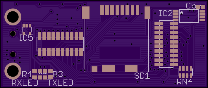
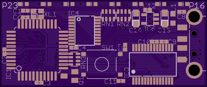
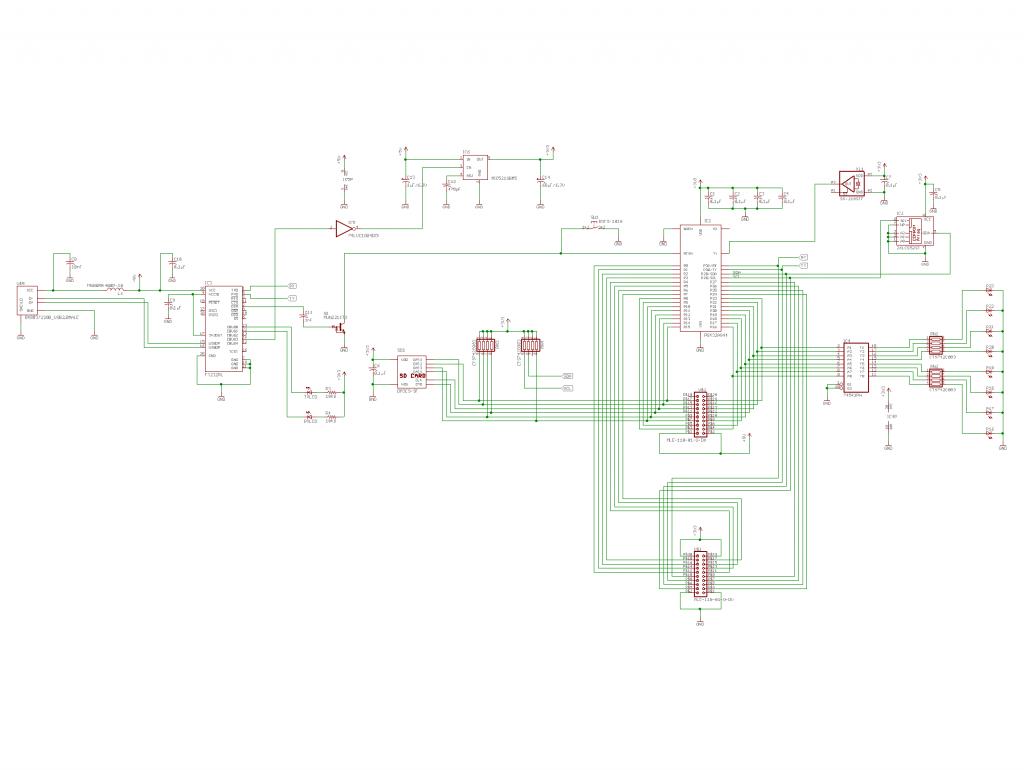
I have included the schematic, and the front and back of the board. Could someone please tell me if I may have forgot something? It is always better to get another(or more) set of eyes, to find mistakes.
Thanks


Comments
Does you CAD pgm do clearance checking ?
Yes it does. The clearance is set to .006" . That is the min OSHpark can do.
Here is a close up. In the selection circle it is .010" apart
There are smaller reset buttons such as Omron KMR4 if that helps create some room.
Generally though, this will be wonderful if you can make it happen. Going to get a ohararp or oshstencils stencil cut? Or pen soldering?
I mostly copied the Prop Plug for the USB, the only thing that is different is I added an inductor that is in the datasheet for the FT232R, and the DTR control. I did what Tracy Allen Suggested.
Thank you for the button suggestion. Trust me, I wish I could use it. I had to go with Omron B3FS series because of the height. I wanted to have access to the button without opening the case, so I had to find a button that would fit in the case, but the push part has to be outside the case. From the board edge, to the inside of the case I have 2.65mm to work with. From the board edge to the outside of the case is 4.15mm. The button I found is 2.6mm for the main part of the button, and the push part is 4.3mm.
I was planing on having OSHstencils make up a set. No way am I trying to lay solder by hand
I have never heard of ohararp, I am going to have to check them out.
Thank you
*EDIT*
I included a PDF of the schematic.
Thanks for the clearer schematic. I couldn't spot anything wrong
Look forward to hearing how it goes.
If you want to Muntz the circuit a bit, you could leave off the pullup resistors on the 4 active SD card lines, and connect together the two unused lines (D1, D2) to one single pullup resistor.
It's not for me to say, but for the intended purpose all pins available externally seems overkill and not too practical on 1mm headers. If you dedicate 4 pins to the SD card, 4 for the tx, rx, sda, scl, and 8 for the leds, that still leaves you with 16 lines to play with that have nothing else going on. Take leds direct to the prop via resistors and get rid of IC4. Get rid of one header or make the remaining one a more congenial size like 2mm or 0.1". The routing and spacing are so much easier.
It's cool. It was my fault, I should've added the PDF from the start. I was just being lazy
Thank you so much. My steadiness is dependent on how much coffee I have had
I knew from the moment I posted about this, that I would be re-doing the whole project. Because I am just one person, with his own ideas (not saying they are right). And I know, that there are a lot of people on here that would have way better ideas than just me alone. I kept asking myself "What would be the benefit of having all 32 I/O's available to me?" I was planing to use the male portion of the headers, and create a "daughter board" that would give me access to the I/O's. I am going to make up another design using your suggestions. I would rather have a min spacing of 0.012", and use 0805 or larger size parts.
Only thinking of the "what if's". I could be wrong, but I would assume hand reworking would be easier with 0805. I might just do the leds in 0805, and the rest being 0603.
http://www.alltechbuzz.com/cuisinart-tob-195-exact-heat-toaster-oven-broiler-stainless/
http://www.smtsolderpaste.com/product-info.php?tin-lead-no-clean-type4-600g-tube-product-page-pid36.html
If you have bridges on the Prop, then use flux on the pins and use a solder pencil to run the bridge out.
That is wonderful, thank you so much for the advice. For the oven, this project would be a great test for my DIY reflow oven, that I am currently working on.
1 minute 175
1 minute 250
1 minute 325
2 minutes 400
1 minute 500
Open door
Using the oven linked above and the solder linked, this provides a very consistent and reliable solder profile that is tried and true over many years. Obviously with a double sided board there is some extra effort involved to glue the parts on one side so they don't fall off.
One suggestion on your schematic, if you really like seeing every connection then that is OK. But you can also put a short net on a pin, name the net, then put a net on another pin you want to connect to, name it the same thing and not reduce both time and effort to draw out your signal. After naming the net, use the label command to place a label next to the net. If you click on the net on one end, it will "light up" at all points that it appears on the board.
My oven I am working on has 2 thermocouples, 2 SSR's, and is able to monitor and control both the top and bottom side temperature of the board. That would allows me to have more options, and make it so the oven can do other things than just reflowing solder.
Thank you for the suggestion on my schematic. I normally do what you suggested, but only if the connections are straightforward. For this one the I/O's don't go to the pinheader in an orderly fashion.
A few suggestions...
You can combine R3 & R4 (use a 5K or 3k3) - while the brightness will vary depending on whether 1 or 2 leds are on, it will save space, and it doesn't matter about the brightness. (you can also use a single led and resistor but 2 leds give better diagnostics)
Forget the inductor on the 5V, replace C8 with 10uF 16V tantalum 0805 (shared with USB input and IC6) and put on input pins to IC6, and route FT232 5V power from the tantalum (not from the USB input power pin, and you can get rid of C13.
Change the regulator to a SOT23 LM1117 3V3 equivalent version or MCP1700T-3302E/TT (forget disabling USB power - while not USB compliant it does not really matter) and remove IC5 & C12.
Change C14 to 10uF 16V tantalum 0805 and place on the output pins if IC6. You can also use X7R ceramic. 0603 are also possible (6V or more)
I like to have a 10K pullup on the props reset pin.
Add 10uF 16V in parallel with C6 at the SD socket pins.
You only require a 10K pullup on CS on the SD socket (other pins do not require a pullup).
Therefore, the RN4 (4x10K) can be used for SDA, SCL, Reset & -CS.
Unless you are really going to try and get parallel SD mode working, you can just connect the CS,DI,DO,CLK (Data In and Out, not 1 & 0).
Not sure what value RN1 & RN2 are - if they are 10K then most likely you don't need IC4 (depends more on your use) and if you really need it then use a 74LVC541 or 74LVC573 or 74LVC245 etc.
Your eeprom pn is mislabelled. I presume you mean 24LC512.
Not sure about XL1. Have you thought about a tiny smt xtal ? CTX839CT-ND is a 6MHz 3.2x2.5mm smt xtal.
I know you have a reset sw. But honestly, I have never used a reset sw, and it takes a lot of space.
I use 0603 regularly now. But you need a little space around them to place them with tweezers, and the pads need to be a little larger for hand placing than m/c placing.
My whole cycle before turning off the heat is 260 secs, and I take the first 180 secs to reach 200C.
I use a pcb under my pcbs to prevent the components on the underside from desoldering and falling off - its to hard to put glue spots for 0603 parts.
It is quite OK. That is why I posted on here, because I know that there are a lot of people that have more experience than I do. And they are willing to share that experience with everyone.
I only did it that way because it was described in the datasheet. I don't have the knowledge or the experience to deviate to far from the datasheet. But I do agree 2 LED's are better for diagnosing. I wanted to put them on the top of the board, but I was having trouble finding a place for them I liked.
I kept questioning myself if it had to be USB compliant. And I only had the regulator being tuned on when the FTDI was connected and active, because I was afraid of inrush currents. But now that I have read what you suggested, and took a step back to think of things. I can see that is a waist, the prop is in low power mode at first power up. and even when the prop boots to full power and everything is on, the FTDI should be connected by then.
I was thinking of that
I had one on it, but I removed it because I did not like the ground path that had to go around it. But now that I am changing things I will make sure it will fit. And I was only following suggestions from SD and others about the 10K's. Did not really know exactly "why" i needed them. Its not like there would be thousands of SD cards going in that slot. The holder I picked is a lift door style. The case would have to come apart, the board taken out, and the SD card door opened to have access to the SD card.
Truthfully, I could not tell you or anyone why I put a SD card on the board, I did it because everyone is using SD cards a lot, and I just wanted to be able learn with it. So I really dont need parallel SD mode, it was just a mode I picked.
I did not have a value yet, since I did not exactly pick the LED's I was going to go with. It was a toss up between red LED's (Personal favorite for LED's), and blue LED's (thinking it would be easier to see). IC4 is a 74LVC541, I just forgot to correct the schematic. I use Eagle CAD, and I will use the closest thing I can find in the library. I will make sure the package is correct, and make sure the pins are correct. If I am happy with what Eagle has, I will just change the value to what I want. Same thing goes for the EEPROM, Yes it is supposed to be a 24LC512. Sometimes I am lazy, and don't feel like making or editing Eagles library. And yes I do know how to. I have been using it for years.
I have never worked with an oscillator before, and I wanted to give it a go. I choose that oscillator because of the small package, the price is not bad, and it comes in a 5MHz and a 6.25MHz version.
I completely agree with you there. I have never needed a reset button. I will just power down, then power up to reset. But I was thinking that since this gets its power from the USB, and lets say I have code that will send something to PST after boot up, if the FTDI is not connected and ready, I could miss the stuff being sent to PST. That is another reason I was thinking of having the FTDI turn on the power when it got connected.
Thank you for all the great advice. I am so glad I came here before I decided to buy the parts, have the boards made, get the stencils cut, and find out I can not put it together. or worse find out that most of the parts have bridged and because of how close they are, can not be fixed.
Also, if anyone has any suggestions of something that could be added to it, please let me know.
Thanks
Thank you for the advice. But I am going with OSHpark to have the boards made, and I am going with OSHstencils for my stencils. I did a quick price comparison with sunstone and OSHpark. OSHpark wants just under $7USD for 3 boards shipped. sunstone wants $586USD shipped for the same specs OSHpark has. ENIG, green mask on both sides, silk screen on both sides.
If you ever use stainless, go without the frame - cheaper and lighter meaning cheaper freight too. Even professional assembly houses dont always use frames.
I use amicroSD socket with exposed pins at thefront in case you need to rework or solder by hand - from digikey - sorry cant recall pn. Its a push pull type,not push push, norhinged.
Maybe you canfind spacefor a HC49U/S xtal - 18pF or 20pF from digikey. Keep the tracks very short, and a ground plane undr thextal. I socket many ofmy pcbsbecause I usually overclock to 104MHz butthis requires pcb layout considerations.
Thank you so much for the advice. I was considering on socketing the crystal.