Shop OBEX P1 Docs P2 Docs Learn Events
Propeller / Raspberry PI experiment board — Parallax Forums

Propeller / Raspberry PI experiment board

RoadsterRoadster Posts: 209
edited 2014-08-27 01:51 in Propeller 1
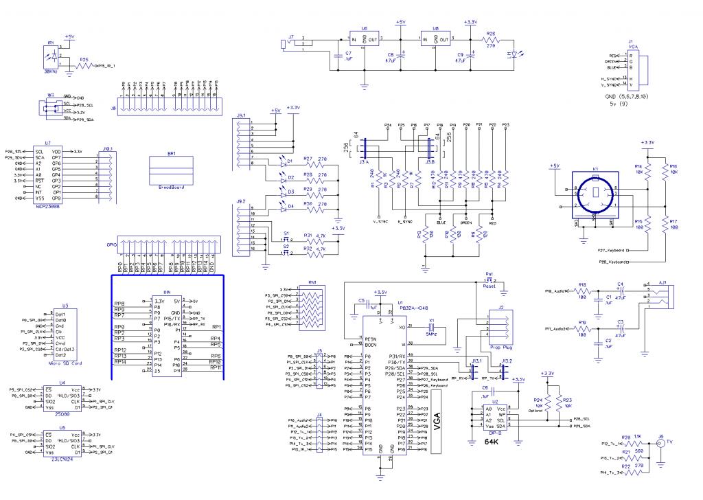
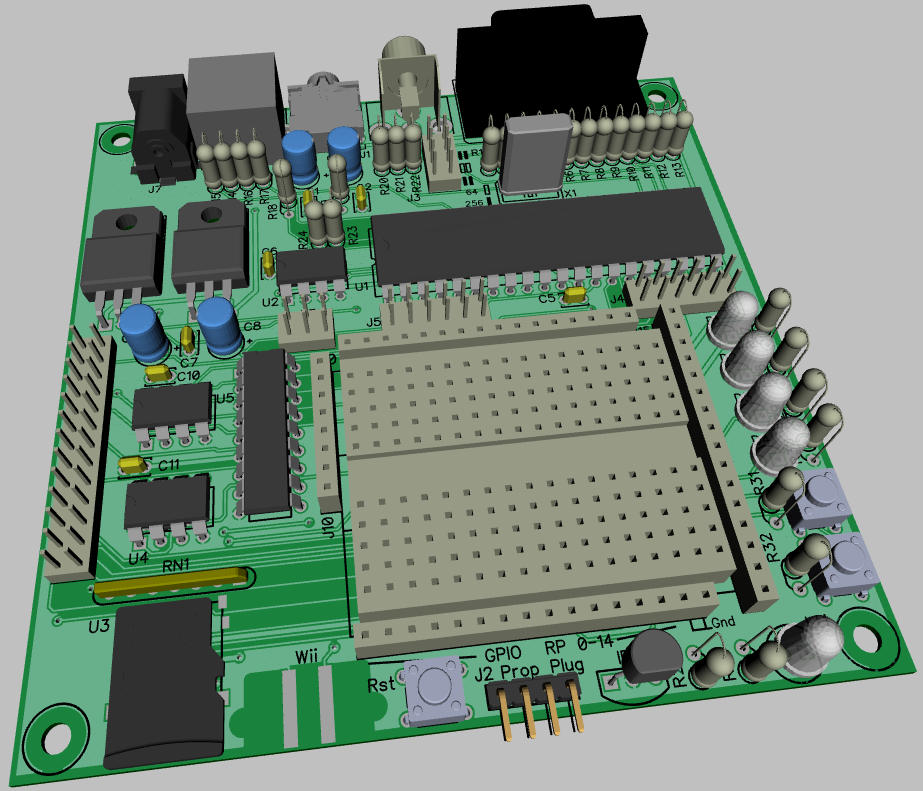
Here Is a board that I have been working on, it has the following features:
VGA 64 / 256 color jumper selectable
Keyboard
Tv pins
Stereo sound
SPI flash 8 pin dip or smd
SPI sram 8 pin dip
micro sd card
IR detector
Wii Connector
Raspberry PI connector

Breadboard area with:
3.3V, 5V and Ground connection
Propeller P0-P15, removable jumpers to disconnect IO connections to Tv, audio, and SPI devices (flash, sram, sd card)
Raspberry PI I/O 0 - 14 I/O 15,16 jumper selectable to propeller serial pins and Propeller plug
4 leds
2 switches
MCP2308 8bit I/O expander
1024 x 728 - 99K
923 x 791 - 250K
«1

Comments

  • TonyWaiteTonyWaite Posts: 219
    edited 2014-04-01 11:50
    Very smart indeed!

    Will you be selling them?

    T o n y
  • RoadsterRoadster Posts: 209
    edited 2014-04-01 13:40
    Once the board has been tested It will be available for sale.
  • David BetzDavid Betz Posts: 14,516
    edited 2014-04-01 20:28
    Roadster wrote: »
    Here Is a board that I have been working on, it has the following features:
    VGA 64 / 256 color jumper selectable
    Keyboard
    Tv pins
    Stereo sound
    SPI flash 8 pin dip or smd
    SPI sram 8 pin dip
    micro sd card
    IR detector
    Wii Connector
    Raspberry PI connector

    Breadboard area with:
    3.3V, 5V and Ground connection
    Propeller P0-P15, removable jumpers to disconnect IO connections to Tv, audio, and SPI devices (flash, sram, sd card)
    Raspberry PI I/O 0 - 14 I/O 15,16 jumper selectable to propeller serial pins and Propeller plug
    4 leds
    2 switches
    MCP2308 8bit I/O expander
    Looks nice! Put me on the list for one when you're ready to sell them.
  • Oldbitcollector (Jeff)Oldbitcollector (Jeff) Posts: 8,091
    edited 2014-06-25 12:57
    We've got a few of these available for purchase.

    http://propellerpowered.com/shop/?page_id=1855
  • David BetzDavid Betz Posts: 14,516
    edited 2014-06-25 19:52
    We've got a few of these available for purchase.

    http://propellerpowered.com/shop/?page_id=1855
    I'm a sucker for anything I can solder together myself. I've ordered one!
  • Oldbitcollector (Jeff)Oldbitcollector (Jeff) Posts: 8,091
    edited 2014-06-25 20:23
    I've added you to the new "Order Tracking page" on Propellerpowered.

    Yours should be ready to go out with Rick's on Friday.

    Jeff
  • David BetzDavid Betz Posts: 14,516
    edited 2014-06-25 20:27
    I've added you to the new "Order Tracking page" on Propellerpowered.

    Yours should be ready to go out with Rick's on Friday.

    Jeff
    Thanks but I'm not in a rush. I'm on vacation for the next few weeks and won't be able to do any computer hacking.
  • Oldbitcollector (Jeff)Oldbitcollector (Jeff) Posts: 8,091
    edited 2014-06-25 20:51
    Shall I allow you order to hold until Tuesday when our second order of parts arrive?

    Jeff
  • David BetzDavid Betz Posts: 14,516
    edited 2014-06-25 20:52
    Shall I allow you order to hold until Tuesday when our second order of parts arrive?

    Jeff
    Sure, no problem.
  • Oldbitcollector (Jeff)Oldbitcollector (Jeff) Posts: 8,091
    edited 2014-06-26 09:09
    Thanks David, I allowed one of the Propellerpowered forum regulars into your spot this morning.


    ... There are four boards left of this order this morning. It'll be 3 weeks after these are out before the next batch. If anyone here wants them, speak up, or I'll feed them to the Tindie hordes.. :)
  • David BetzDavid Betz Posts: 14,516
    edited 2014-06-26 10:02
    Thanks David, I allowed one of the Propellerpowered forum regulars into your spot this morning.


    ... There are four boards left of this order this morning. It'll be 3 weeks after these are out before the next batch. If anyone here wants them, speak up, or I'll feed them to the Tindie hordes.. :)
    I'm confused. Your earlier message said you wanted to put my order on hold until Tuesday but now this message says the second batch of boards won't arrive for three weeks. When do you expect to ship my order? It isn't a big deal. I just want to know when to start looking for it.

    Thanks,
    David
  • Oldbitcollector (Jeff)Oldbitcollector (Jeff) Posts: 8,091
    edited 2014-06-26 10:14
    Sorry about the confusion! Don't worry, yours is going out in the first batch on Tuesday. :)

    I made a last minute decision to package the microSD kit as part of the main kit. When I ran the numbers, there was room to include it.
    Because of that, several units are on hold until Tuesday (including yours) while we wait for our part order.

    After this batch is gone, then it'll be 3 weeks until the next batch of PCBs. :)

    Jeff
  • David BetzDavid Betz Posts: 14,516
    edited 2014-06-26 10:18
    Sorry about the confusion! Don't worry, yours is going out in the first batch on Tuesday. :)

    I made a last minute decision to package the microSD kit as part of the main kit. When I ran the numbers, there was room to include it.
    Because of that, several units are on hold until Tuesday (including yours) while we wait for our part order.

    After this batch is gone, then it'll be 3 weeks until the next batch of PCBs. :)

    Jeff
    Okay, thanks for the clarification. I'm looking forward to being able to use a single board to do what I used to do with the old PMC three-board stack.
  • David BetzDavid Betz Posts: 14,516
    edited 2014-07-12 09:47
    I got my kit. Are there assembly instructions online somewhere?
  • David BetzDavid Betz Posts: 14,516
    edited 2014-07-12 09:48
    David Betz wrote: »
    I got my kit. Are there assembly instructions online somewhere?
    Never mind. I found them myself: http://propellerpowered.com/forum/index.php?topic=587.0
  • David BetzDavid Betz Posts: 14,516
    edited 2014-07-12 17:10
    I'm starting to put together the Propeller/RPI Experiment Board and have a question. There are a number of dual headers on the board but the kit only came with single row headers. If I have dual row headers is there any reason I can't use them in place of two single row headers side by side? Is there some reason single row headers were included?
  • mindrobotsmindrobots Posts: 6,506
    edited 2014-07-12 17:17
    No reason. They are easier to solder as duals. I hooked the singles together with the jumper blocks in places they were calling for duals. Easier to solder when physically held together.
  • Oldbitcollector (Jeff)Oldbitcollector (Jeff) Posts: 8,091
    edited 2014-07-12 17:29
    Single row headers are a little easier to work with when cutting to proper size. The kit could just as easily come with dual headers for those positions and probably not influence kit costs. but it's kitted to my taste. It really didn't occur to me to use dual row when I'm so used to working with singles. :) I didn't even use @mindrobots trick when putting it together. I personally love "painter's tape" for holding parts to the board while I'm working, so you might notice that the kit had an extra amount of tape included when holding the sockets down to the foam in the package?

    Jeff
  • David BetzDavid Betz Posts: 14,516
    edited 2014-07-12 17:44
    Single row headers are a little easier to work with when cutting to proper size. The kit could just as easily come with dual headers for those positions and probably not influence kit costs. but it's kitted to my taste. It really didn't occur to me to use dual row when I'm so used to working with singles. :) I didn't even use @mindrobots trick when putting it together. I personally love "painter's tape" for holding parts to the board while I'm working, so you might notice that the kit had an extra amount of tape included when holding the sockets down to the foam in the package?

    Jeff
    Yes, I noticed the painters tape. Thanks!
  • David BetzDavid Betz Posts: 14,516
    edited 2014-07-12 19:21
    Ummm... Where does the green LED go that came with the main kit? I must have missed the step where that is installed.

    Edit: I downloaded the schematic and that cleared up everything. Got the kit assembled. I'll try powering it up tomorrow. Also, it looks like I should probably populate U4 and U5 to allow for a flash and SRAM chip to be added. Nice!

    One more question, what header is supposed to be used for the i2c connections to P28 and P29. I didn't see a two pin female header in my kit.
  • mindrobotsmindrobots Posts: 6,506
    edited 2014-07-12 20:33
    I think it is still a missing step in the instructions.

    LT1 - the power LED (down in the corner by S2)
    R26 - 240ohm resistor

    Prop plug connector is also unlabeled - Rx goes on the pin right next to the J2 label (Gnd (VSS) goes under the "G" in "plug" :smile:)
  • mindrobotsmindrobots Posts: 6,506
    edited 2014-07-12 20:39
    David Betz wrote: »

    One more question, what header is supposed to be used for the i2c connections to P28 and P29. I didn't see a two pin female header in my kit.

    I cut one of the female headers to size - 8 for J10(?) and then 2 for the I2C.
  • David BetzDavid Betz Posts: 14,516
    edited 2014-07-12 20:44
    mindrobots wrote: »
    I cut one of the female headers to size - 8 for J10(?) and then 2 for the I2C.
    I didn't get any extra female header to cut. Mine exactly fit the other four slots. I have some of my own though so I will cut one of those down to size. If I decided to add the flash and SRAM chips, I'm assuming that C10 and C11 are .1 uf capacitors, right?

    Edit: Also, should the RPI header be male?
  • mindrobotsmindrobots Posts: 6,506
    edited 2014-07-12 20:49
    I believe so. That's what I put in there, anyway. My flash and SRAM chips went missing.....so I haven't tested those yet.

    Maybe I ended up cutting my own header too - I don't remember...but I did cut headers!! :smile:
  • David BetzDavid Betz Posts: 14,516
    edited 2014-07-12 21:02
    mindrobots wrote: »
    I believe so. That's what I put in there, anyway. My flash and SRAM chips went missing.....so I haven't tested those yet.

    Maybe I ended up cutting my own header too - I don't remember...but I did cut headers!! :smile:
    Okay, I did that and now all I need to do is find a couple of 8 pin sockets and some .1 uf capacitors to get the flash and SRAM working. Also, a header for the RPI in case I decide to hook that up.
  • David BetzDavid Betz Posts: 14,516
    edited 2014-07-12 21:09
    OBC: Do you by any chance have a kit that contains the MCP23008 and its socket? I don't think I have any 18 pin sockets handy. Actually, a kit to complete the board would be nice. It could include the RPI header, the MCP23008 with socket and at least the sockets and caps for the flash and SRAM.
  • David BetzDavid Betz Posts: 14,516
    edited 2014-07-13 04:56
    All done except for the I/O expander chip. I don't have that chip or even an 18 pin socket. Now I just need to get up the nerve to power it up. I installed the flash and SRAM chips so I should be able to get this working with PropGCC with the xmm-split memory model.

    pmc.jpg
    1024 x 768 - 149K
    pmc.jpg 149.3K
  • Heater.Heater. Posts: 21,230
    edited 2014-07-13 05:13
    Roadster,

    I don't want to appear too negative. This looks like a great board. It would be fine as a stand alone Propeller system.

    But I have a few questions regarding it being a Raspberry Pi experimenter board:

    1) Why have the video outputs? The Pi already drives TV and HDMI and they are normally used with that.

    2) Similarly why have the audio outputs? The Pi already does that.

    3) Similarly why have the SD card? The Pi already has one.

    4) Similarly why have a keyboard interface?

    The breadboard area seems like a great idea. But then again why the I/O expander? A Prop added to the Raspi GPIO is already a big I/O expander for the Pi.

    Edit: Of course if one want to use a Pi with a VGA screen this board is a good way to get a terminal interface.
  • mindrobotsmindrobots Posts: 6,506
    edited 2014-07-13 05:46
    @heater, all features don't need to be used at the same time. It does let you take one board and use it for multiple experimenter purposes.

    If you are not hooking it up to a RasPi, you have easy access to mote of the things folks connect to a Propeller plus a small breadboard area.

    It is a stand alone terminal if you want, it is a stand alone retro style Basic computer if you want.

    Pull all the jumpers and you have a simple Prop board with a Prop Plug, EEPROM and 28 free I/O pins.

    Put on the RasPi jumpers and it is connected via the RasPi pins to the console Rx/Tx via pin 30 and 31.

    Use as much as you want or as little as you want depending on your need - I thought it was a pretty clever design from that standpoint.

    Mine is currently set up to be a stand alone terminal for working with the MicroMite MMBASIC chip.

    peb-mup-1.jpg


    If time permits this afternoon, I'm going to try and hook it up to my STM32F4 running Espruino so it can be the programming front end to that. (Hey, you guys were all talking about a new board combining an ARM and a Prop. This is certainly an easy jumping off point for that experimenting...or should I not use it because I won't be using the RasPi connector or the SRAM and port expander? I think I will use the SD card but not the audio or the IR....gosh, what to do??
    1024 x 768 - 133K
  • David BetzDavid Betz Posts: 14,516
    edited 2014-07-13 07:37
    I'd like to try the MicroMite chip plugged into the breadboard area. I think OBC has already done this but I can't find the thread giving the wiring diagram and software. Can someone point me to it?

    Thanks,
    David
Sign In or Register to comment.