

3D Printed 28BYJ48 Stepper Moter Actuator ( Low cost EcoRobo Series)

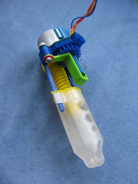
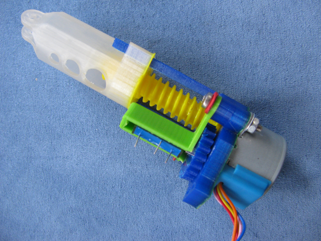
Here is a custom 3D printed Linear actuator for activating a lever or push/pulling something or other.
It uses a Cost effective Stepper motor (we all know which one).
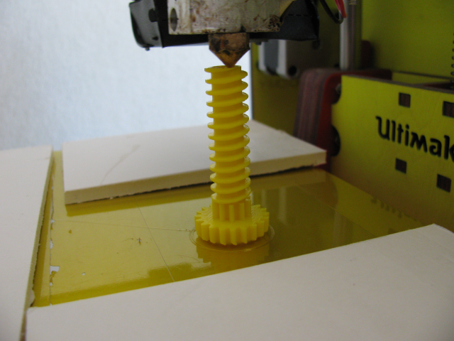
From a previous static test i knew that the motor in this worm screw configuration could push close to 2Kgs of force (as measured against my kitchen scales)
The bugbear was thinking of a way to attach a feedback potentiometer to the worm screw...
....I tried linear potentiometers however they were limited in length...
. .... instead I used a 10 turn Linear Pre-set Potentiometer and geared it further down with spur gear.
I designed It using "Blender" ... sticking to a general 0.2mm for clearances so everything slotted glove-like together.

Printing took a 2 hours, plus 2 more for tweaking .
Eco_Friendly Note :- When my print is under-way I place heat insulating foam around the print piece ...
..this stops the cooling fan dropping the temperature of the Heat-Platform unnecessarily, conserving Watts.
.. It also reflects heat back into the Heat-Platform and helps maintain a stable base heat.
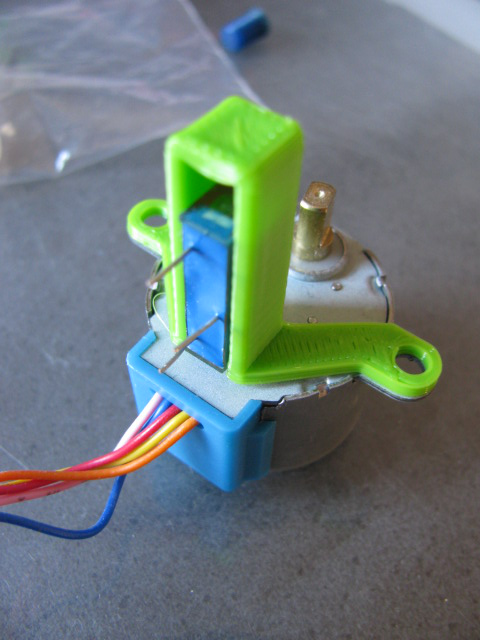
Close-up of the Feedback pot .... its the key to the miniturisation . I have left circa 5mm room for adjustments.

I am pleased with the design (although I plan a few upgrades to add extra performance)

I have wired up the system and after a test run I am pleased with how precise the feedback potentiometer is. YAY
Assembly Walkthrough :-
[video=youtube_share;0WFP2zGRc9E]
It uses a Cost effective Stepper motor (we all know which one).
From a previous static test i knew that the motor in this worm screw configuration could push close to 2Kgs of force (as measured against my kitchen scales)
The bugbear was thinking of a way to attach a feedback potentiometer to the worm screw...
....I tried linear potentiometers however they were limited in length...
. .... instead I used a 10 turn Linear Pre-set Potentiometer and geared it further down with spur gear.
I designed It using "Blender" ... sticking to a general 0.2mm for clearances so everything slotted glove-like together.
Printing took a 2 hours, plus 2 more for tweaking .
Eco_Friendly Note :- When my print is under-way I place heat insulating foam around the print piece ...
..this stops the cooling fan dropping the temperature of the Heat-Platform unnecessarily, conserving Watts.
.. It also reflects heat back into the Heat-Platform and helps maintain a stable base heat.
Close-up of the Feedback pot .... its the key to the miniturisation . I have left circa 5mm room for adjustments.
I am pleased with the design (although I plan a few upgrades to add extra performance)
I have wired up the system and after a test run I am pleased with how precise the feedback potentiometer is. YAY
Assembly Walkthrough :-
[video=youtube_share;0WFP2zGRc9E]
480 x 640 - 411K

640 x 480 - 401K

640 x 480 - 420K
480 x 640 - 580K
640 x 480 - 602K
Comments
Nice work.
At first I read this as the "Low Cost ERCORobo Series" but ECO works too!!
No, Gareth has long surpassed me with his robotic prolificity and he can name his manifold creations as he sees fit.
Well done AGAIN, Brother Gareth. Do you ever sleep?
Indeed this is so.... there are many things to be be designed out there.....it only needs a "tad" extra effort..... (ie not to get stuck in the .... lets print me a new printer that will print me a new printer loop ...which is often the case).
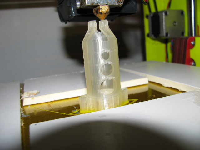
The design was my first go at combining many things together in one part....the centre screw bit has four parts .... and was a "Pig" to knit the interfaced layers (gears) together ....
....sleep...yes ..however the coolio designs happen unfortunately just before sleep onset.....
regards Sir Gareth of the round table.
I know these steppers are slow, so I must assume that this is not a high speed device. Aiming a telescope, or tracking, perhaps? Gotta see some video!
Next print I will increase the infill ie much more than the 10% I used in the prototype you see...
The Stepper chastity belt was an easy clean up .... except for these neat furry bits..... I could not resist taking a photo :-
Specs :-
40mm (1.5") linear motion (It uses only 25% of the feedback pot ... meaning the leadscrew could be extended to 160mm (6 and 5/16")
Travel time 40mm =
Working Torque :- 1Kg continuous (although I know this stepper will achieve 2Kgs)
Hmmmm... maybe I'll rapid-fabricate my own linear actuator using the all-too familiar purple Hot Wheels track clamp that holds orange track to a tabletop. You know the one!
As Great "Bros" think alike ..... here is what is already sitting in the background .....all bases are covered.....there is something awaiting in the shadows......
That's just the Solarbotics motor I was thinking about.
Amanda <green with envy>
Added assembly Video in main description.
Now looking for deployment possibilities...