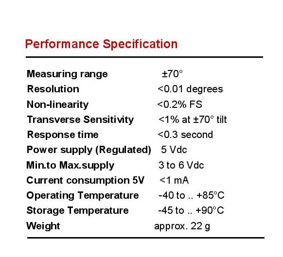
Convert 5v analog signal to 3.3v
I am having sensor Inclinometer it specification attached below. it output varies from 0-5v . 0 degree read at 2.5v , +70 @ 5v and -70 @ 0v from output side.I have micro controller chip kit uno32 Analog input pin of 10 bit resolution Which can read voltage between 0-3.3v. Question Here:
I have drop the volatge from 5v to 3.3v using voltage devider network using R1=504ohm and R2=980ohm


- How to convert 5v sensor output to 3.3v to match its resolution.??
- I have also tried to used to drop 5v output to3.3v using diode. How it will affect the sensor output voltage??
I have drop the volatge from 5v to 3.3v using voltage devider network using R1=504ohm and R2=980ohm

int sensorPin = A0;
float Yvoltage;

static float ARDUINO_ANALOG_SCALING =0.00322265625;
static float Ydegree;
static int Sensor_Value;
static float Xdegree;
float Xvoltage;

void setup()
{
  Serial.begin(9600);
}
void loop()
{
 Sensor_Value=analogRead(A0);
 Serial.print(" Sensor vlaue:");
    Serial.println(Sensor_Value);

 Yvoltage = Sensor_Value * ARDUINO_ANALOG_SCALING;
   Serial.print(" Y voltage:");
    Serial.println(Yvoltage);
    Ydegree=(30*Yvoltage)-75;
    Serial.print(" Y degree:");
    Serial.println(Ydegree);
     Serial.println("......................");
    delay(1000);
}


Comments
A diode is a non-linear device, so it won't work right. Its response will vary along a curve.
Your voltage divider schematic is good, but you may have to adjust resistor values to get a stable reading. This is a question of how much of a load the sensor outputs can tolerate. Your values may be fine or a bit low.
5/3.3 = total resistance/the 3.3 volt resistance
So you might try a higher total resistance, such as 5000 ohms or 10,000 ohms.
Right now, 504 ohms + 980 ohms equals 1484 ohms at 5 volts, so you are loading the sensor at about 3ma output. The microcontroller input can easily handle less.
Ideally you want a 500 ohms and 1000 ohms. You can double and triple that to 1000ohms with 2000ohms or 1500ohms with 3000ohms and so on.
Is that 3ma too high a load or okay?
With the right values and ratio of resistors, you will get what you want... a linear response.
-Phil
I amusing above board . I tried with above resistance value . USing program i am getting improper value . I am getting -75 degree at 0v and 2.8v i am getting 0 v but other 3.3v i could not able to achieve 75 degree.
Try higher resistors -- say 2000 ohms and 4000 ohms to make the load below 1 ma. If that doesn't work, go even lower.
+++++++++++
Ummm, if you are getting -75 degrees and expect 75 degrees, you might have just made a math mistake in your programing. The senor might be doing fine.
To choose the divider you need to know about your source impedance but for the moment let's just assume it is around 1K to be safe but it would of course help if you gave a link to the inclinometer.
Now even if we only present a 1/10 of the load by using the equivalent of 10K load it will still introduce error but let's just work with that.
So R1+R2 = 10K and at max voltage of 5V --> 500uA
Therefore R2 = 3.3/500uA = 6K6 and that leaves 3K4 for R1 (the input).
Now you can fudge these values up or down a bit to match up with standard values but I would just use two 3K3s in series for the 6K6 and and 3K3+100R in series for R1. Place a 0.1uF across R2. Try that and measure the FS voltage with a meter.
VIN
3K3----100R
>ADC
...............................|
3K3----3K3
GND
...............................|
104
GND
int sensorPin = A0; float Yvoltage;static float ARDUINO_ANALOG_SCALING =0.00322265625;static float Ydegree;static int Sensor_Value;static float Xdegree;float Xvoltage;void setup(){ Serial.begin(9600);}void loop() { Sensor_Value=analogRead(A0); // Result = 0 - 1024 Serial.print(" Sensor vlaue:"); Serial.println(Sensor_Value); Yvoltage = Sensor_Value * ARDUINO_ANALOG_SCALING; // Result = 0 - 3.3V Serial.print(" Y voltage:"); Serial.println(Yvoltage); Ydegree=(30*Yvoltage)-75; // Change to Ydegree = 45.45 * (Yvoltage - 1.65) Serial.print(" Y degree:"); Serial.println(Ydegree); Serial.println("......................"); delay(1000);}
Then you can change the sensor supply voltage to 3.3V (Min.to Max.supply 3 - 6 Vdc
OR
you can configure the divider to R1 = 2010 ohm (2000 ohm + 10 ohm) and R2 = 3900 ohm
I hope you are making progress, but wish you were actually using a Propeller.
On the topic of bringing over to propeller, perhaps some articles and contributions to say Maker pubs like the arduino interface chapter in the "Getting Started With the Raspberry Pi" would be a great help to getting people to do more with props and Pi Just a thought for widening the market for the propeller.
FF
Not possible send exel-files as attachments?