

3D printed Touch Sensor - Cost effective Displacement type

This is a displacement resistance type touch sensor.
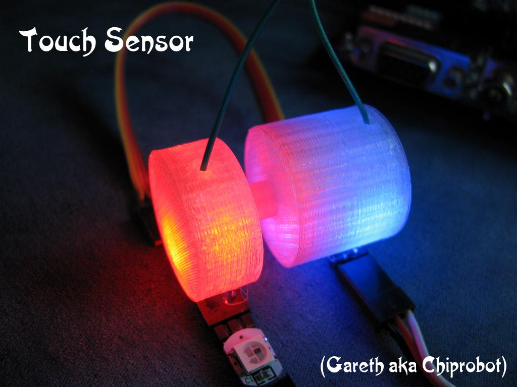
It uses conductive foam as the resistive element.
The resistance can be easily tailored and tweaked to your needs.
If you would like to see a video Walk-through of how to build the Sensor it can be found here :-
[video=youtube_share;ylJovLCM3DY] [/video]
This is what you will need :-
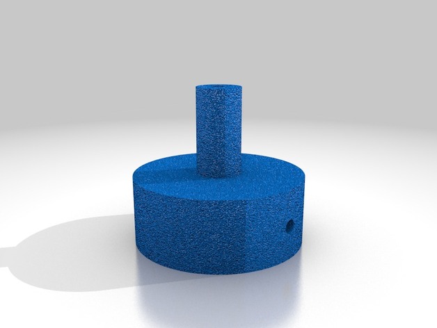
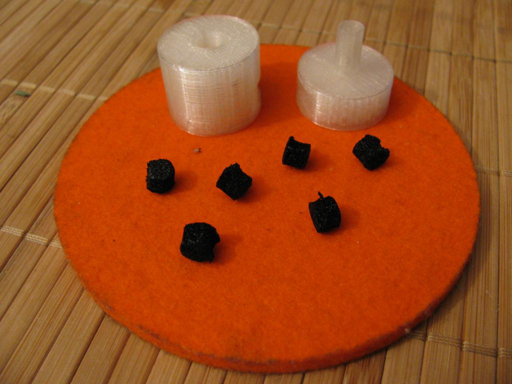
Firstly a pair of these of these 3D printed parts :-
Touch Sensor - Cost effective Displacement type


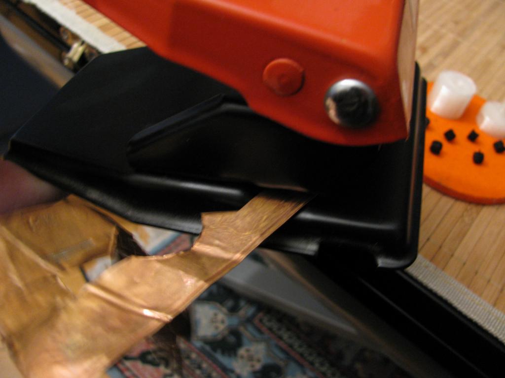
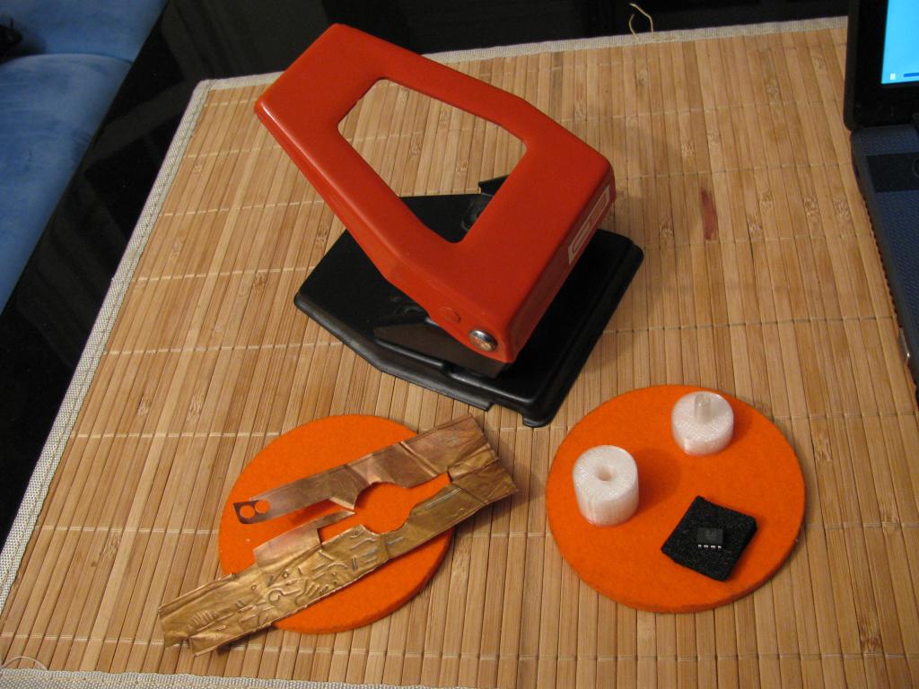
You will need a simple A4 paper Hole puncher.

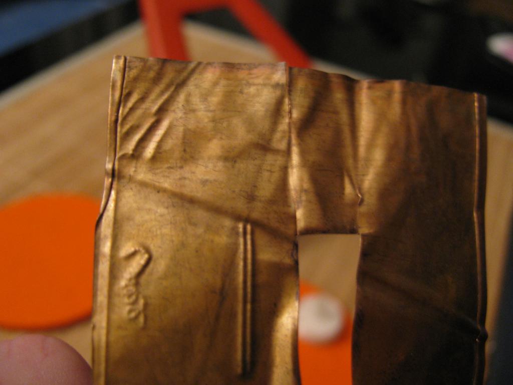
A small sheet of flat thin copper (or tin at a pinch ... just remember that a wire has to be soldered to it)

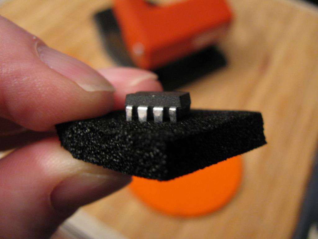
A small piece of "Conductive Foam" , this foam is commonly found as an antistatic foam used for shipping integrated circuit chips. It is a black foam - if you are not sure then just probe it with a multimeter turned to the "Ohms" scale..(remember that different foams will have different qualities and resistances)

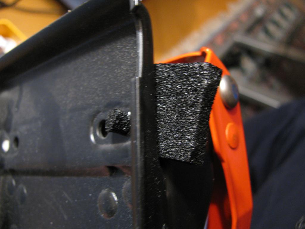
Use the hole punch to punch 4 to 6 cylinders of the conductive foam.

Use the hole punch to punch 2 discs out of the copper sheet.
It uses conductive foam as the resistive element.
The resistance can be easily tailored and tweaked to your needs.
If you would like to see a video Walk-through of how to build the Sensor it can be found here :-
[video=youtube_share;ylJovLCM3DY]
[/video]This is what you will need :-
Firstly a pair of these of these 3D printed parts :-
Touch Sensor - Cost effective Displacement type
You will need a simple A4 paper Hole puncher.
A small sheet of flat thin copper (or tin at a pinch ... just remember that a wire has to be soldered to it)
A small piece of "Conductive Foam" , this foam is commonly found as an antistatic foam used for shipping integrated circuit chips. It is a black foam - if you are not sure then just probe it with a multimeter turned to the "Ohms" scale..(remember that different foams will have different qualities and resistances)
Use the hole punch to punch 4 to 6 cylinders of the conductive foam.
Use the hole punch to punch 2 discs out of the copper sheet.

1024 x 768 - 75K
1024 x 768 - 105K
1024 x 768 - 50K
1024 x 768 - 59K
1024 x 768 - 67K
1024 x 768 - 76K

1024 x 768 - 58K
628 x 472 - 47K

628 x 472 - 35K
Comments
Feed some wire into the 3D printed base and plunger.
Solder the Wire (I used CAT5 Ethernet inner wires - as they are plentiful and easy to come by and they have a good threading ability ) onto each of the copper disks.
Feed the conductive foam carefully into the base unit until you get the desired feel of the touchiness (or resistance value)
Insert the plunger into the base units and "There You Go" a Resistive Displacement Touch Sensor.
I attached some NeoPixels to give some direct indication of the state of the sensor..... "Shine_ing"
That is it, now just use your imagination for some applications...
Terrific and fun project, anything with hands-on interactive lights & sound is an attention-getting crowd pleaser. I know you have at least one son, I hope you are able to get this and more of your other great creations into his and other kids' hands to spark creative thinking. You ought to teaching! And don't forget writing about a few articles for SERVO magazine. Keep up the excellent work!
Have you done any endurance testing? I've read this sort of conductive foam can breakdown with repeated use.
I need to figure out a way to miniaturize this technique to use the sensors on the tips of my hexapod. I'm hoping touch sensitive feet would help walk over uneven terrain.
How are you doing your ADC? Sigma-delta?
I am using for convenience a MCP3208 on my propeller as it provides 8 Channels of 12Bit Analog to Digital conversion..
I am currently making a Loonnng version, which will have around 3cm displacement (I hope) , I think this would be more in the direction of your spider legs... will keep you posted.
Regards G
Indeed my son is programming in quite a creative way. He was tap_ped at an early age with "Logic" which seems to have paid off...
....Yes_yes...Servo mag..its on ToDo list.
Not so much miniaturized....... however thin_naturized ...
Maybe the sensor can double as a leg...
Specs :- 72.64mm resting >1 MΩ
60.50mm compressed ≈15KΩ