Building 3D Models for DipTrace (and other programs)
 JonnyMac
Posts: 9,621
I'm now hooked on having 3d models for all the components of my DipTrace projects -- like most, I just see things differently when I can rotate a model of my PCB in 3D space. Where I struggled was modeling with Wings3D which is recommended by the DipTrace folks.
To cut to the chase, I came across the suggestion to use a program called OpenSCAD (Open S-CAD) which is a modeler for programmers. Instead of dragging things around with a mouse, one writes C-like description code. For example, I'm helping a friend with a Propeller-based camera controller that has a separate HMI board with an LCD and lighted buttons. I couldn't get my head around modeling the button in Wings3D, but after 15 minutes of YouTube tutorials on OpenSCAD, I was able to create a dimensionally accurate button -- this is what that code looks like:
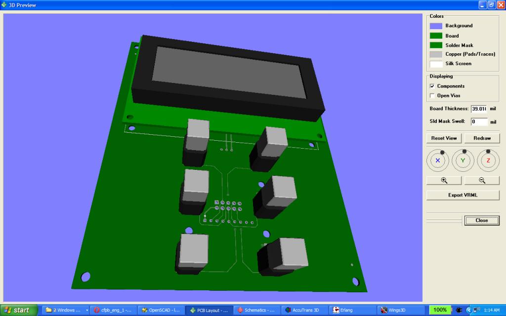
I've attached a screen-shot from the DipTrace 3D view. I built the LCD in OpenSCAD as well -- this is the code.
As was pointed out in the Kicad tutorial that led me to OpenSCAD, the STL export from OpenSCAD crashes Wings3D which I use for finishing and final VRML export. I'm using a program called AccuTrans3D to open and resave the STL. This gets loaded into Wings3D for finishing (add color, bevel edges) and final export for use in DipTrace, Kicad, etc.
To cut to the chase, I came across the suggestion to use a program called OpenSCAD (Open S-CAD) which is a modeler for programmers. Instead of dragging things around with a mouse, one writes C-like description code. For example, I'm helping a friend with a Propeller-based camera controller that has a separate HMI board with an LCD and lighted buttons. I couldn't get my head around modeling the button in Wings3D, but after 15 minutes of YouTube tutorials on OpenSCAD, I was able to create a dimensionally accurate button -- this is what that code looks like:
// Lighted push-button
// Digikey 563-1240-ND

// base
//
translate([0, 0, 6])
{
  intersection()
  {
    cube([9.9, 9.9, 12], true);
    rotate([0, 0, 45]) cube([12, 12, 12], true);
  }
}

// support
//
translate([0, 0, 12]) cube([7, 7, 7], true);

// button
//
translate([0, 0, 23-9/2]) cube([8.6, 8.6, 9], true);
I've attached a screen-shot from the DipTrace 3D view. I built the LCD in OpenSCAD as well -- this is the code.
// 4x20 backlit LCD
// Digikey 73-1249-ND

// base pcb
//
translate([0, 0, 0.8]) // half pcb thickness
{
  difference()
  {
    cube([98.5, 61, 1.6], true);
    translate([ 46.25,  27.5, -1.5]) cylinder(3, 1.4, 1.4);
    translate([ 46.25, -27.5, -1.5]) cylinder(3, 1.4, 1.4);
    translate([-46.25,  27.5, -1.5]) cylinder(3, 1.4, 1.4);
    translate([-46.25, -27.5, -1.5]) cylinder(3, 1.4, 1.4);
  }
}

// frame/glass
//
translate([0, 0, 9.5/2+1.6])
{
  difference()
  {
    cube([92.2, 37.6, 9.5], true);
    translate([0, 0, 8.5]) cube([76, 25.2, 9.5], true);
  }
}
As was pointed out in the Kicad tutorial that led me to OpenSCAD, the STL export from OpenSCAD crashes Wings3D which I use for finishing and final VRML export. I'm using a program called AccuTrans3D to open and resave the STL. This gets loaded into Wings3D for finishing (add color, bevel edges) and final export for use in DipTrace, Kicad, etc.


Comments
// Lighted push-button
// Digikey 563-1240-ND
http://www.digikey.com/product-detail/en/CFPB-1CC-4W9W/563-1240-ND/2357726
// 4x20 backlit LCD
// Digikey 73-1249-ND
http://www.digikey.com/product-detail/en/C-51847NFJ-SLW-AEN/73-1249-ND/769330
I am using OpenScad for a while now. For me it is way easier to 'program' a 3d model then build it with graphical tools. That scripting language is easy yet quite powerful.
I import the stl direct into my printer software and had not had any problems there. The printing itself is another issue. not easy with bigger things.
The nice thing is that you can use parameters and sub routines. Fun to play with.
Enjoy!
Mike
I'm just scratching the surface but have seen that it really looks like it's going to be a lot of fun. For the most part, I will be creating models for DipTrace so that I can get an idea of what my PCB will look like, or I can show the person that I'm creating the PCB for (as in this case).
About two weeks ago I needed a small piece of plastic to fit snuggly over three 5mm LEDs that were mounted to a PCB; the purpose of the plastic was to hold a bundle of fiber optic cables to be lit by the LED. Luckily, Rick Galinson (the guy who built the Propeller-powered paintball mini-gun) is a good friend. I popped over to his house, described what I needed, and about 10 minutes later he machined one, then sent the other to his 3D printer (big pro job he uses for build movie and tv props) while we went to get a bite to eat. I often need a little tchotchke that I cannot fabricate myself; I think with OpenSCAD I'll be able to create what I need.
And it's not as if I need another excuse to write code....
http://www.cs.princeton.edu/~min/meshconv/
BTW I came across this site last night that has free 3d components and I thought I would pass it along, all you need to do is register for free, use the search download your selected format
http://www.3dcontentcentral.com
I've also found that some manufacturers have models. On that board is a Hirose uSD socket, and that model came from Hirose.
There is no longer a need to pull the model into Wings3D to add colors (as I had to do with OpenSCAD models); that can be done in FreeCAD. The only extra step is having to open and re-save the VRML file with AccuTrans so that it displays properly in DipTrace. Small step and it works.