Adding DC Motor Control to the Activity Board
 Copper
Posts: 48
Prologue:
I started working on my first robot approximately forever ago. The Goal is to build a robot that can locate a 1.5" cube on a ~1.75' X ~4' table, without falling off, and then relocate the cube to a 3" red paper circle[taped to the table].
I'm using an Activity Board for the controller.
So far it can find the block.
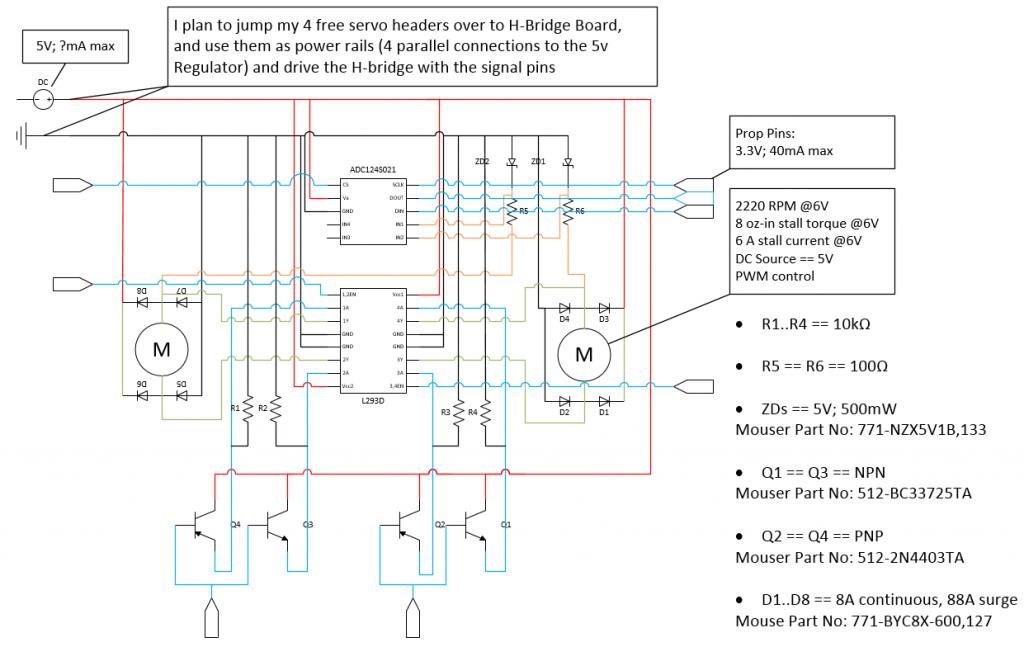
Now I need to add an H-bridge (plus a few things), and wire up my DC motors. I think I have a fair bit of it figured out, but I'm concerned about the two NPN/PNP transistor pairs [bottom of the diagram below]; what I want to accomplish, is to have 1 prop pin translate to 2 pins, 1 of which will always be high, and the other low.
so you have line A, and B controlled by a prop pin(P)
P|AB
1|1 0
0|0 1
I'm sure people do this all the time.
Really I appreciate any feed back.


Comments
Or if you use a 74HCT14 you can run it at 5V supply and have it recognise 3.3V input
signals from the Prop and level-shift to 5V
Anyhow, you are driving a lot more and you need something "beefier" to handle this, perhaps even discretes. I don't know why you have selected 5V for the motors, normally you run them straight off the batteries, certainly never off a regulator and especially never ever off the same regulator that goes to the processor.
There are plenty of chips and circuits around if you want more information. The inverter is the very least of your worries.
I'm totally new to all of this. With PWM, is there a relationship between %on and "available" current? If I'm driving the motor at 50%, does that reduce the stall current the motor draws?
I could easily change to 2A stall current motors (available in the same form factor). Unfortunately, the L293D's peak output current is ±1.2 A. I'll look around and see if there are some "beefier" H-bridges that can handle 2A (I imagine there are. Plus they aren't my main drive motors, I only use them to actuate the claw (obviously I could have used servos, but I wanted the opportunity to tackle both with this project)).
Oops. The L293 does not. I was looking at the wrong schematic.
Neither do I really. I am totally new to this. I'm using an activity board for the brain of the robot, because I can't build my own from scratch. So I was trying to use as much of it as possible. It seemed natural that if I can drive 5V servos from the servo headers, I should be able to drive 5V DC motors. I'll admit I don't understand current very well either (I was assuming (me:=***) the PWM/Stall current relationship I asked about above existed, and that by driving the motors slowly (which I want anyways) I would also limit the current they could draw).
If I need to connect my DC motors directly to the power supply, I have some serious work/reading to do.
There's tons of information out there. The problem is I only have one lifetime to get through it all. If you have any recommendations for chips or resources, I would greatly appreciate it.
Also, thanks for the Inverter suggestion Mark_T, that sounds great (I had a feeling there was a better solution).
The L293B has a Peak Output Current (non-repetitive) of 2A. I'll never be driving both motors at the same time. If I also switch to the 2A stall current motors (which I'll probably never drive past 50%), that might be a reasonable drop in replacement for the schematic above (like the L293, the L293B has no diodes).
Updated Schematic.
As for the motor power supply, it looks like the Activity Board has jumper selects on the servo ports so they can be 5V or VIN. I would just need to add a 5V regulator to the circuit.