

DIY microSD adapter for practically nothing

Hello all,
There are hundreds of different tutorials out there for making a microSD card adapter. Well here is my version.
I needed to store a lot of data, and the 64KB EEPROM I had was not big enough. So I decided to use A SD card. I found a few on eBay with the help of people here on the forum, and the price was not that bad. For less than $2 you could have one delivered to your door, in a few weeks. I didn't want to wait, so I looked around my apartment and I found a microSD adapter. I sat and looked at it, and I realized the pins were just about the same spacing as my pin headers.
I went onto Parallax's site, and found the schematic for there SD adapter. I noticed that I must have 10KΩ resisters on the data lines. Now, I dont like having to look for extra parts when I want to do something. I have countless other stuff that I use for prototyping that has support parts soldered to it. Why should this be any different?
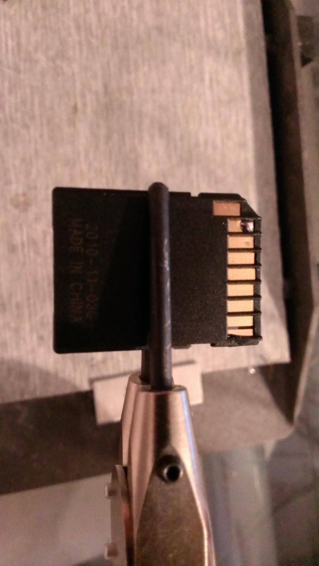
I started with the microSD adapter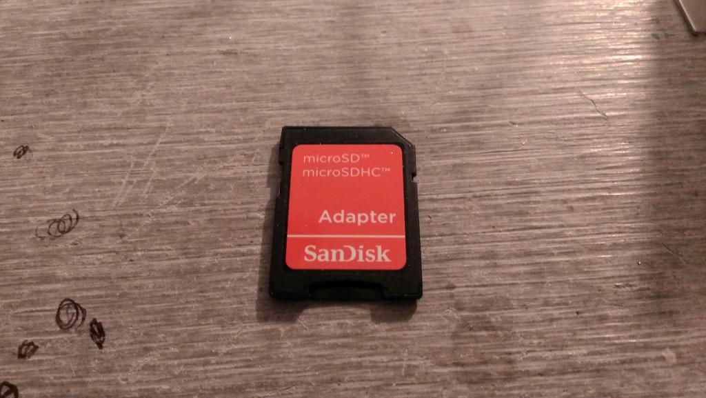 . I then put a little solder on one of the pins. I did that to hold the header in place, and to figure out what would be my best way to solder to the pins.
I then started on the support parts. Looking at the schematic, Parallax has 8, 10KΩ resisters. But I dont have CD pin, or a WP pin. so that is 2 resisters I don't have to worry about. Then I decided I would use SPI protocol. That meant, 2 more resistors could be forgotten. So that is 4 resistors, and a .01µF cap.
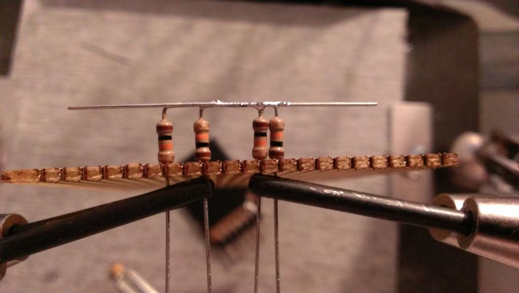
For the support parts I started with the resistors. I took 4 resistors, and bent a 90 on one leg of each.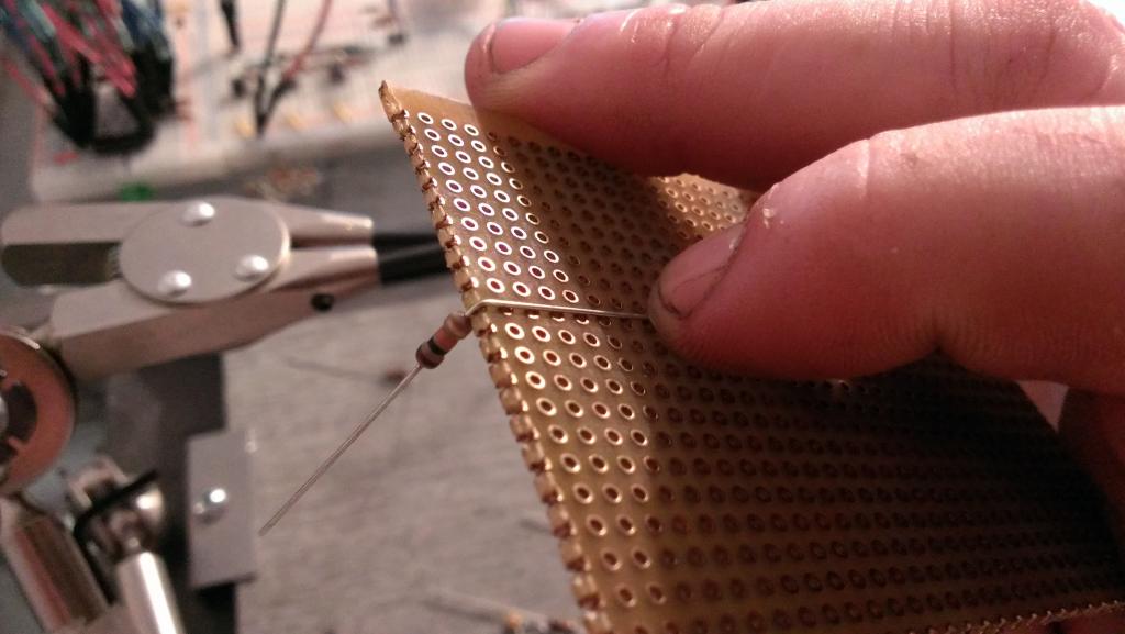 I then used my perf-board to align the resistors. I started with the 2 that are right next to each other(CS, and DI).
 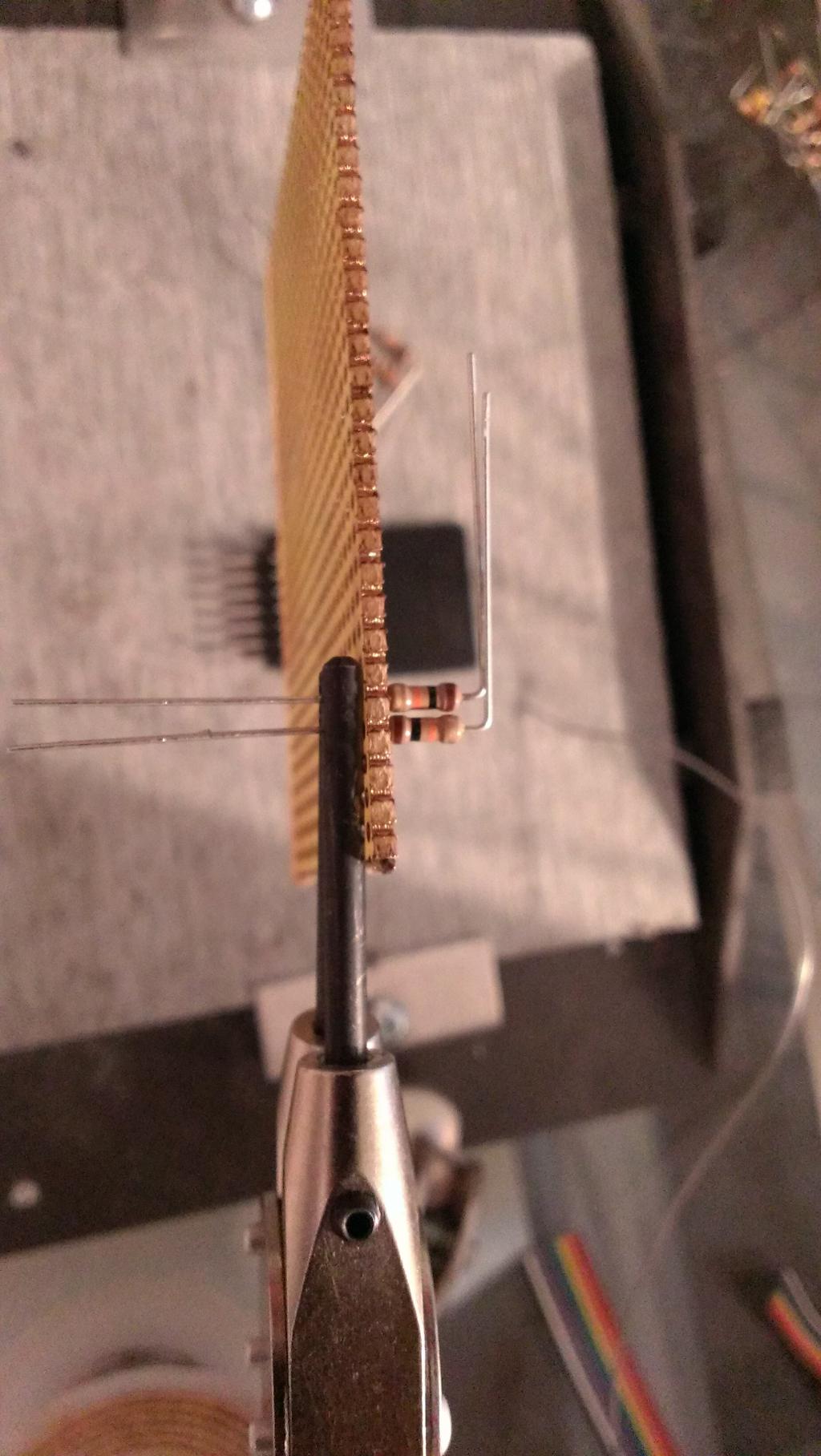 I trimmed the outside lead to match up with the other resistor lead, the soldered them together.
 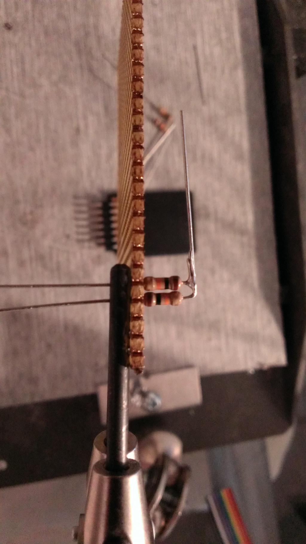 I did the same thing with the other 2 resistors. I then soldered both batches of resistors together.
  I took one of the leads I cut from one of the resistors and added A leg for the 3.3V so the resistors are being pulled HIGH.
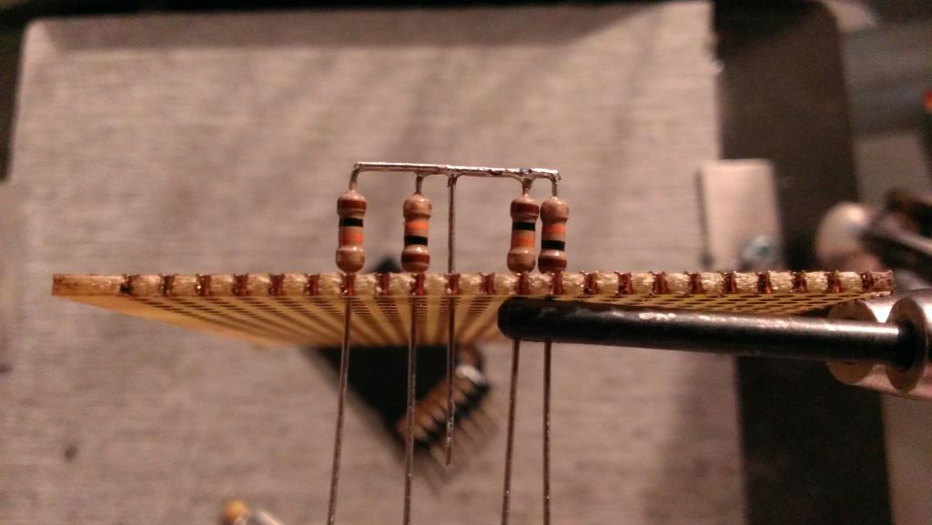
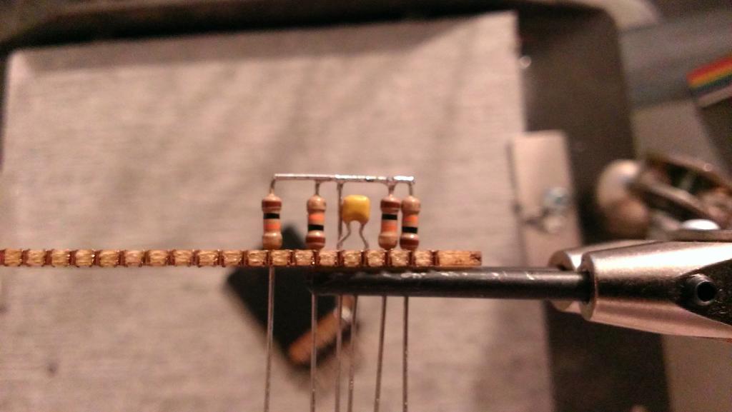
I continued with adding parts by adding the .01µF cap to the 3.3V leg, and where the GND pin would be. I then took more leftover resistor lead and made a jumper for the second GND pin, I added some heat shrink tubing to protect it from shorting anything out.
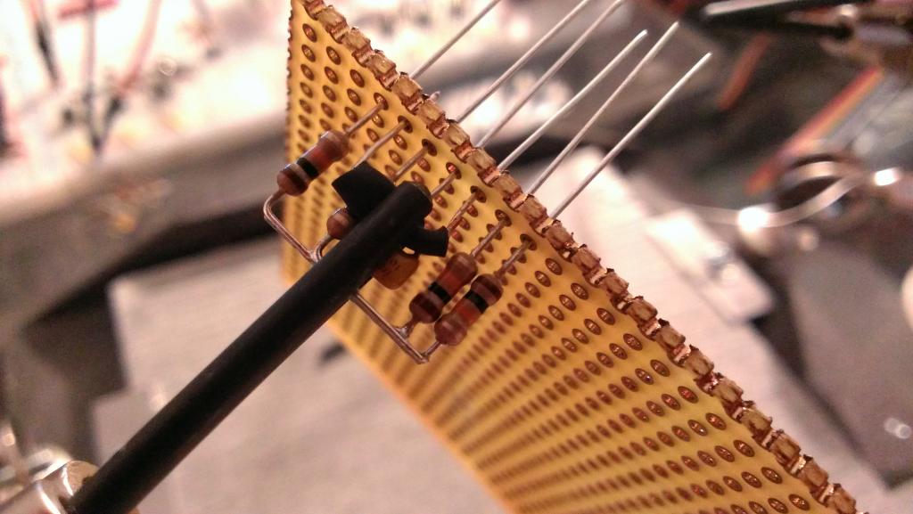 I know I probably didn't need to add the jumper, but I also didn't want to take the chance and find out later that the pins were not hooked together inside the adapter.
There are hundreds of different tutorials out there for making a microSD card adapter. Well here is my version.
I needed to store a lot of data, and the 64KB EEPROM I had was not big enough. So I decided to use A SD card. I found a few on eBay with the help of people here on the forum, and the price was not that bad. For less than $2 you could have one delivered to your door, in a few weeks. I didn't want to wait, so I looked around my apartment and I found a microSD adapter. I sat and looked at it, and I realized the pins were just about the same spacing as my pin headers.
I went onto Parallax's site, and found the schematic for there SD adapter. I noticed that I must have 10KΩ resisters on the data lines. Now, I dont like having to look for extra parts when I want to do something. I have countless other stuff that I use for prototyping that has support parts soldered to it. Why should this be any different?
I started with the microSD adapter
I then started on the support parts. Looking at the schematic, Parallax has 8, 10KΩ resisters. But I dont have CD pin, or a WP pin. so that is 2 resisters I don't have to worry about. Then I decided I would use SPI protocol. That meant, 2 more resistors could be forgotten. So that is 4 resistors, and a .01µF cap.
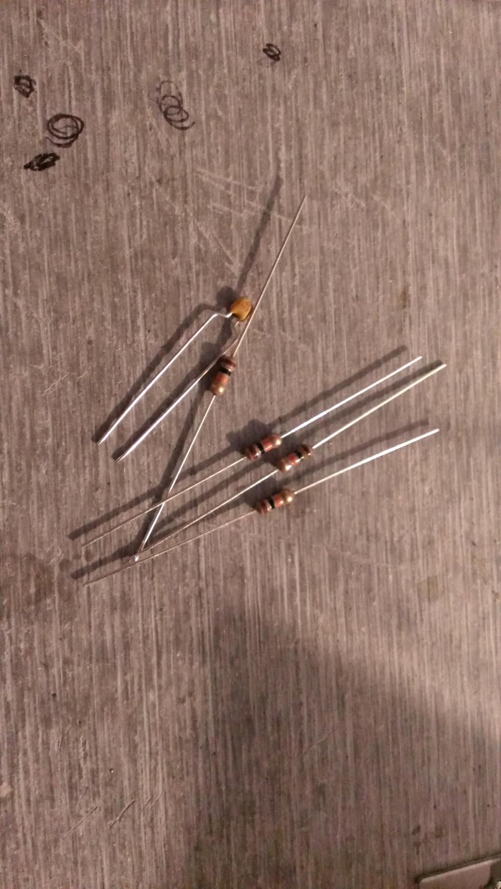
For the support parts I started with the resistors. I took 4 resistors, and bent a 90 on one leg of each.
I continued with adding parts by adding the .01µF cap to the 3.3V leg, and where the GND pin would be.

1024 x 577 - 80K
1024 x 1816 - 137K

1024 x 577 - 61K
1024 x 1816 - 221K

1024 x 1816 - 171K

1024 x 1816 - 158K
1024 x 577 - 53K

1024 x 577 - 53K
1024 x 577 - 52K

1024 x 577 - 74K
Comments
Now to test it. I plugged it into my breadboard, followed the AppNote, loaded the prop, and waited for the program to complete. After it was done, I tried the microSD card in my computer and was able to see the file the prop added to the microSD card.
Now I know there are much better products out there, Parallax has a good one. But I am happy with this one, and I think it will give me many years of usage.
I have over 1000 10K resistors. But I only have .01uF caps.
You do wonderful work.
You also came to the right place for help and advise.
If I may ask, what type clamping are you using in those pictures?
Tim
Thank you very much for the kind words. This was my first attempt at documenting something I built. The part came close to what I wanted (little messy for me), but the documenting could use a lot of work. Only time will fix it.
I completely agree with you. There are some great people here that have helped me a lot.
Sure, no problem. You can find it HERE. It is a little pricey, but not as much as I have seen for vices. I got the idea from a jeweler friend of mine more than 10 years ago. It is heavy(maybe 6-7lbs), the gray block on the bottom is fire proof(no burning my bench from the iron), the clamps are great for holding little parts and wire. It takes some effort to move the arms(they stay where I put them). My hands shake a little, and my eye sight is not the best. but with this clamp, I can bring the thing I am working on up to me, and I can steady my hand by resting it on one of the arms.