Does anyone know what this is?
 TC
Posts: 1,019
Hello all,
I came across something I thought was cool. I don't know what it is used for, and Google is not much help. I found the company, but not this item. From what I can tell, this thing is from the 80's. I was hoping someone on here knows. Here are some pictures.
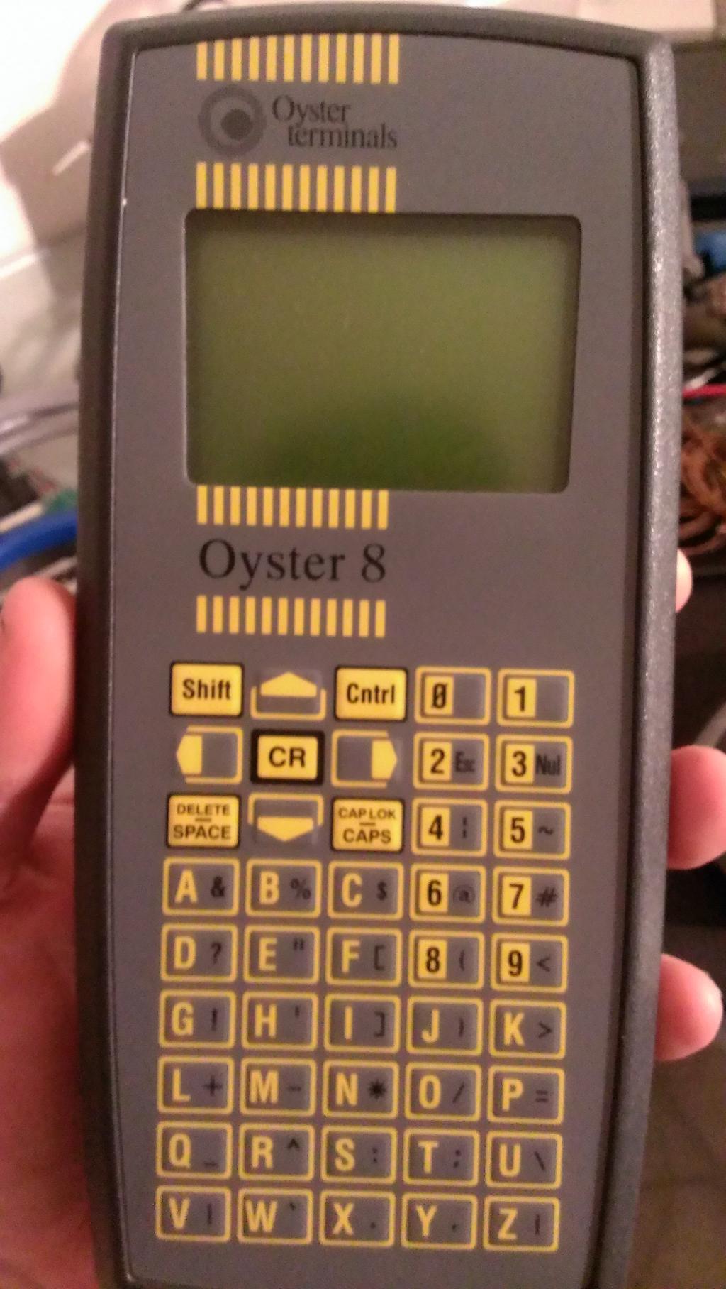
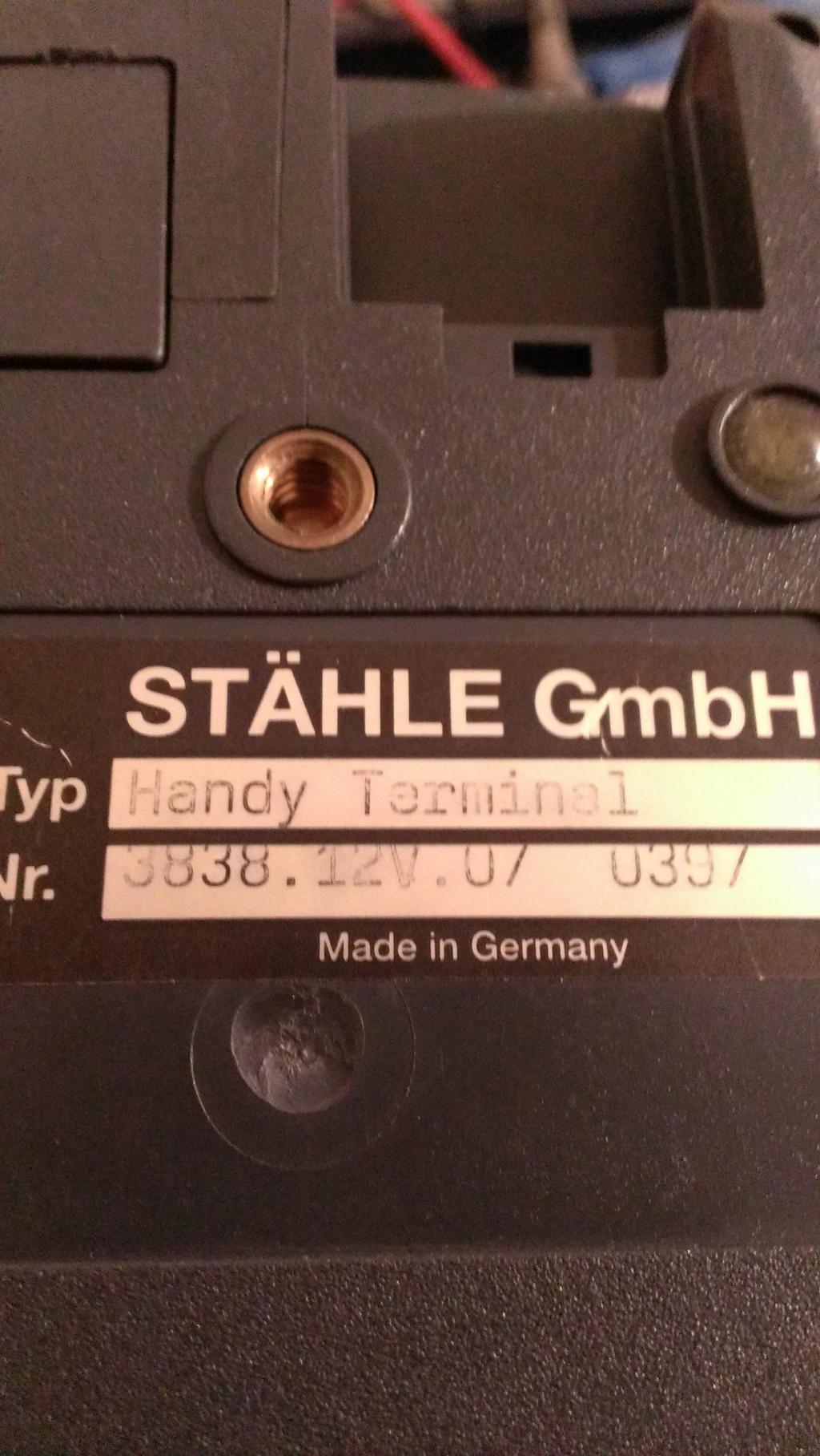
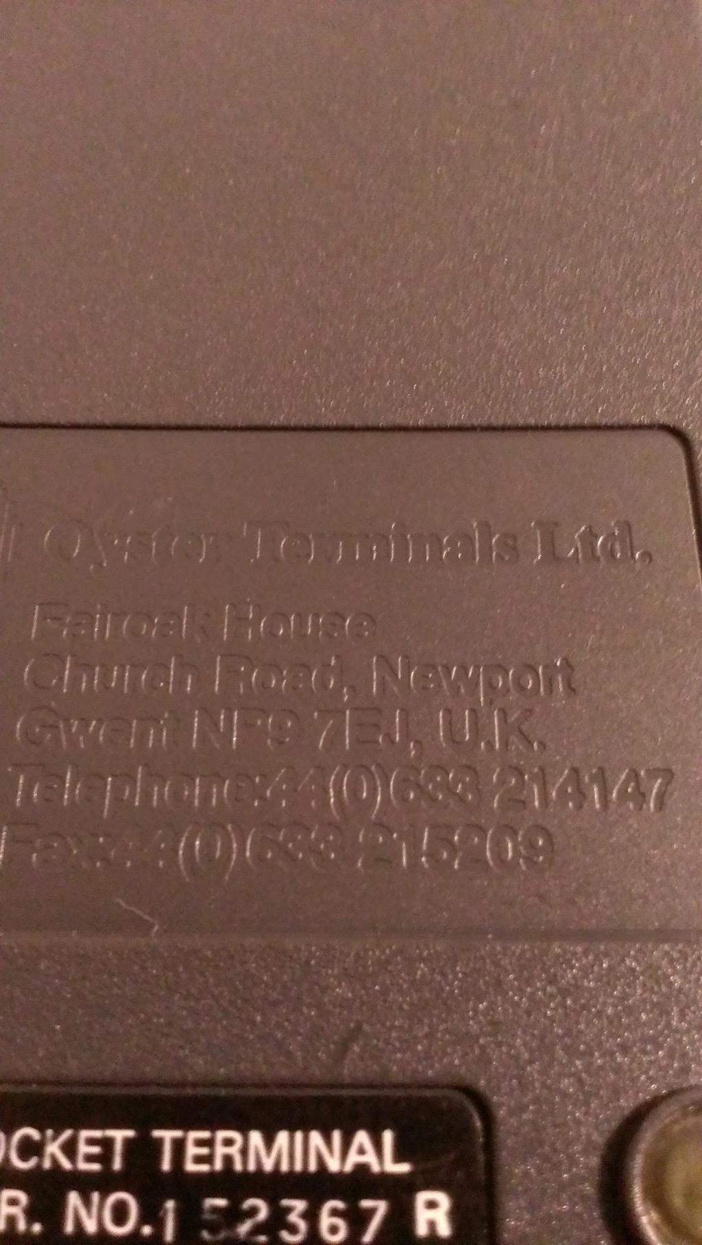
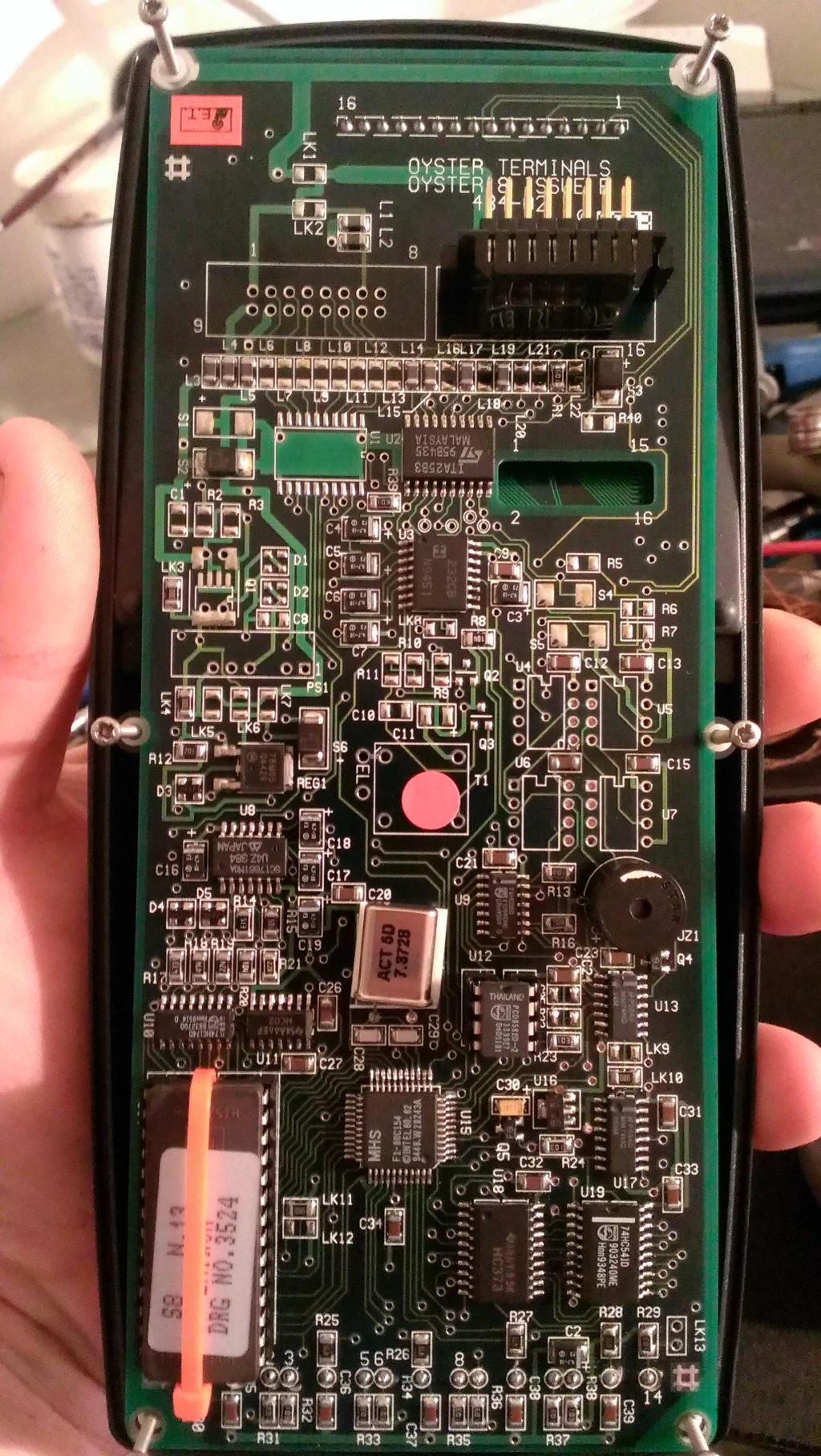
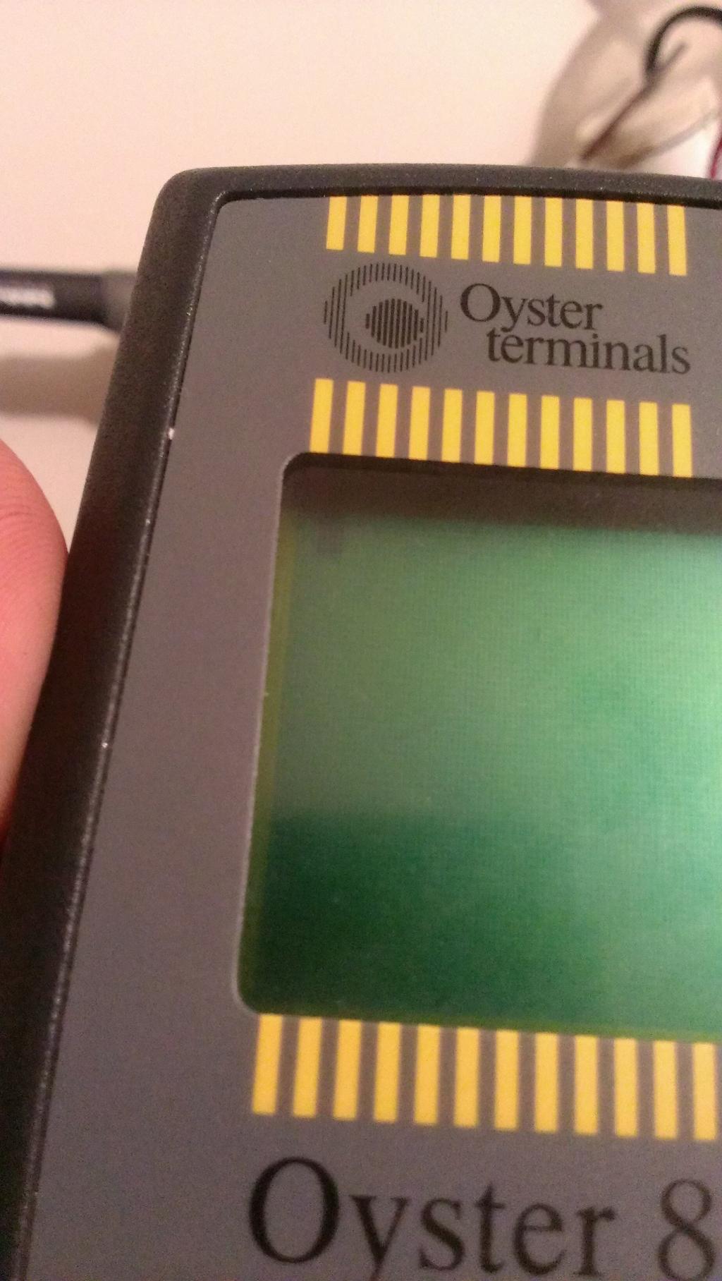
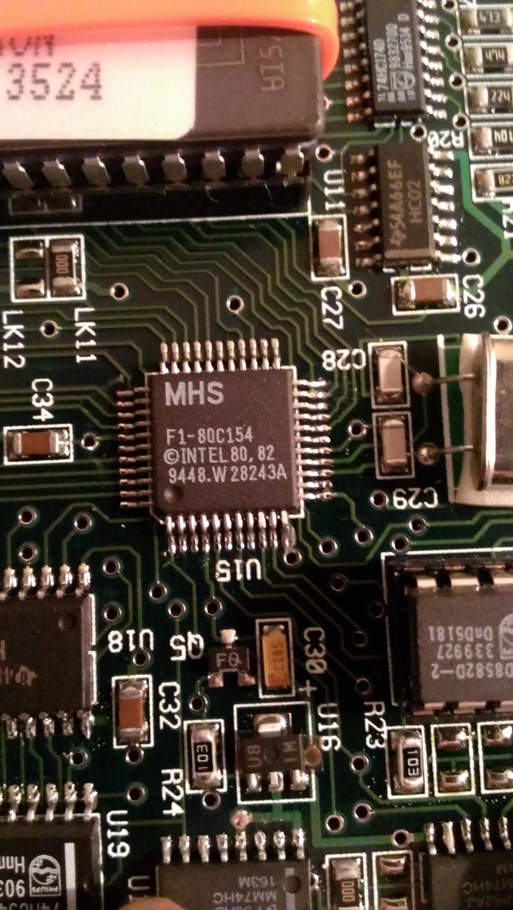
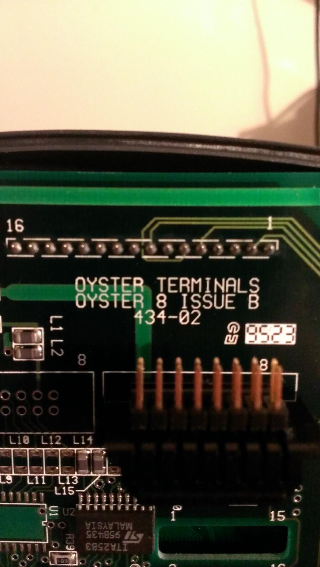
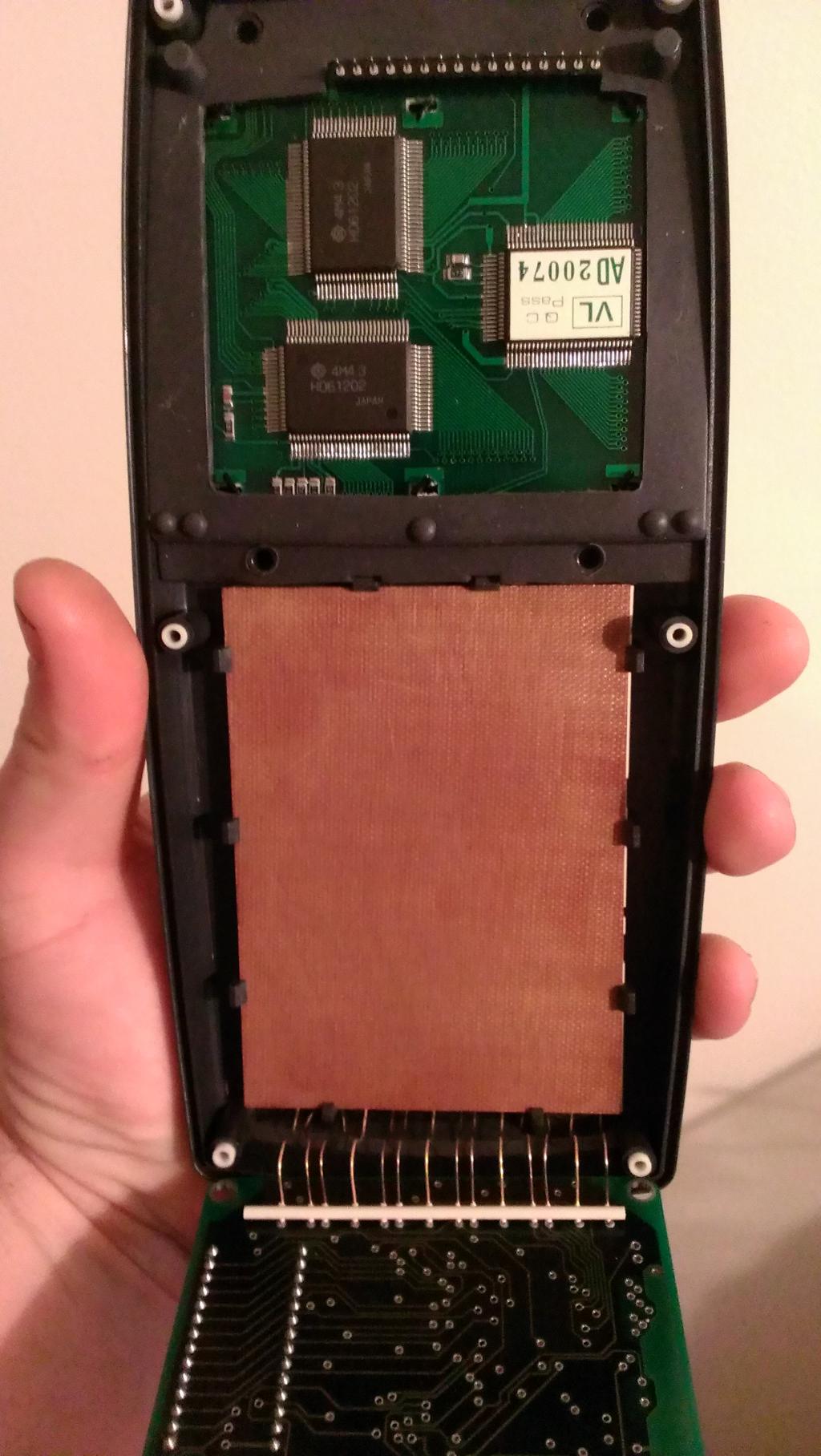
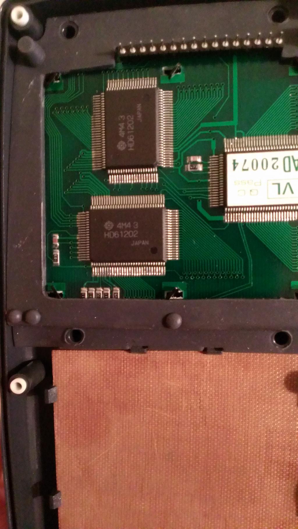
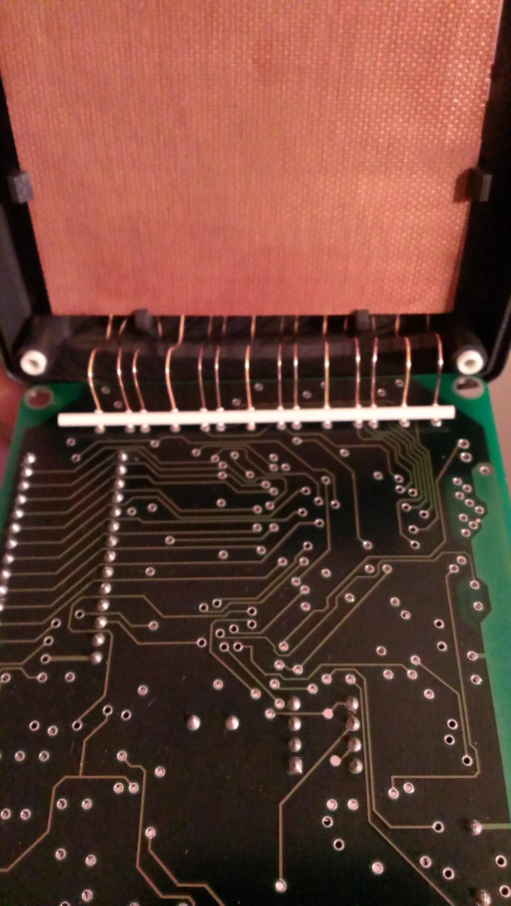
I got it to power up. The display will just show a blinking cursor. When I push any button, the thing will "beep". I hooked a LED(+resistor) to one of the remaining 2 wires (4 total), and every time I push a button, the LED will flash for a split second. I am thinking it is some kind of serial communication.
What do you guys think? What do you think I could do with it(possible project)?
Thanks
TC
I came across something I thought was cool. I don't know what it is used for, and Google is not much help. I found the company, but not this item. From what I can tell, this thing is from the 80's. I was hoping someone on here knows. Here are some pictures.


I got it to power up. The display will just show a blinking cursor. When I push any button, the thing will "beep". I hooked a LED(+resistor) to one of the remaining 2 wires (4 total), and every time I push a button, the LED will flash for a split second. I am thinking it is some kind of serial communication.
What do you guys think? What do you think I could do with it(possible project)?
Thanks
TC


Comments
http://www.oysterterminals.co.uk/
Tha'ts the web site Google provided me. But they have no info on there. And I can almost bet, they will not tell me anything.
I thought it might of been from the 80's. Guess I was wrong.
It does not seem to have rf com but could have had the stored data scanned optically.
Otherwise I guess it is a naval clunk maker<G>.
(Romless version of the 80150 series 8bit microcontroller. An evolution of their 8050series)
I think this is a 'generic' model they customised for a customer, since you can see an almost identical one on this page:
http://www.oysterterminals.co.uk/customisation.html
They've just added some decor and a EPROM.
Are there any connectors on the outside(top/bottom edges)?
Any accessories?
What about batteries?
As far as what to do with it, I can see 4 options...
1. Hack it apart and use the parts in different projects. Kind of wasteful, really.
2. Find yourself an EPROM programmer, an 80150 assembler and make a program for it...
(Expect to use a lot of time just figuring out how to access the built-in peripherals)
3. Use it to baffle friends...
4. Sell it to someone who's nerdy enough to collect stuff like this...
(I must admit that I don't own one of these... )
I can't really remember any such systems coming out of Germany at that time. It's more likely that they just hired a German company to do the manufacturing. (This was made in a time when quality meant something)
It could be interesting to do a dump of the onboard EPROM...
OOPS! I knew I would forget something.
Brown = +12VDC
Grey = ground
Pink = Rx
Green = Tx
I hooked it to my old, tired stamp works board
pushing letter "A" on unit, and on keyboard
Output is in HEX format
On the keyboard, at a baud of 9600, if I push numbers from 1 to 7 I get on the screen in this order
Likewise, If I push 1 to 7 on the handheld, I get the same thing on the PC.
[/quote]
As far as what to do with it, I can see 4 options...
1. Hack it apart and use the parts in different projects. Kind of wasteful, really.[/quote]
Agreed!
I don't have the experience to do that.
I could do that. But I am not looking for money, I am looking for logic devices so I can experiment with. And not just the normal AND, OR, NOT etc... the special stuff, DECODERS, COUNTERS, RAM, etc..
I would never hack it up. it is to cool to destroy. It would be nice to figure out the commutation and use it that way.
That could be used as an input and display device for various gizmos "out in the field". For many things they just had a circuit board controlling something. (Those would need to be set-up initially or settings changed every now and then.)
Say a lawn sprinkler controller, traffic signal, security system, air conditioning system, etc. Anything with a control board.
These days they include an input device and display with everything. Previously you needed a separate terminal. Also they had "shared" computers which might have had 30 terminals connected. So something like that handheld terminal might have been used on a factory floor whereas other people connected to the same computer would have a desk size keyboard and monitor.
Pin 5 is normally CTS(Clear to Send)
Have you tried 2400bps, and maybe varied between 7 / 8 bits, and messed with the number of stop bits?
Does the text received change if you send the same character more than once?
Since you have a BS2 available, you could us that to read out the EPROM...
Pull the EPROM, and place it in a solderless breadboard.
Hook the DATA pins to IO on the BS2.
You can hook the remainder of the IO on the EPROM's 'Output Enable', and low end ADDRESS pins.
The leftover address pins you tie down for now.
Write a program that loop while it counts up on the address pins, and read off the data, then sends it over the serial link to your PC.
When it finishes, change the tie downs of the upper part of the address bus to read another block, and rerun program...
Or if you have a couple of HEX counters, chain them together until you have enough outputs for every address pin on the EPROM, and just toggle a single IO on the BS2 to 'step' through the contents of the EPROM
I agree with you on the RS-232 part. I found this
Possibly...
Don't ask me how many times back in the 90s or early 00's people fund me sitting 'Buddha style' in a cramped closet that was he local excuse for a server or network room, with my trusty Psion S3a PDA in my hands and a horrible tangle of cabling going to a router or something...
(I needed the 'soap on a rope' cable that worked with the PDA, a male-to-male null-modem cable, and then the equipment manufacturer's own cable. And sometimes a 9 to 25 adapter )
Routers and switches still has serial console ports, for those times when you really can't reach them on the net...
Nope, not for a factory floor setting.
This handheld probably cost MORE than a cheap PC of the time...
(limited production runs... custom SW... long lead time on an order for a replacement... )
So if it was used on a factory floor, it would have had other functions, too.
I have an ancient Norand 100 handheld that's possibly from before 1980. (It uses an Intel 8048 mCU, more commonly found in keyboards)
It was used in brand name garages in the USA. They punched in part numbers while doing the work, and afterwards, they hooked it up to an acoustic modem, and sent the parts order to a central computer.
It only had a 'one way' modem, though, and the user had to listen in to the synthesized voice in the other end to verify the order.
Yes I did. 2400 did nothing, and on the ones that did do something, I tried 7bits, 8bits, 1 stop bit, 2 stop bits, even, odd, nothing changed.
It would just display the same character the same amount of data sent. like I was pushing the key more than once.(hope that makes sense)
I have one better. I have a prop I could use. and I also have a txs0108e level translator, to make sure it will work.
I will work on trying to get the ROM data and post it. I've never done this before, but it will be a good learning experience.
Sounds like cheating to me...
mostly, because my BS2 has a few pins that don't work right. It is my first BS2 from years ago.
The numbers on the DATA and ADDRESS pin on that EPROM... They're suggested use, really.
(I know of equipment where they swapped things around to simplify the PCB layout.)
It doesn't hurt to check that they connect to the mCU in the right order.
I did that. the address lines are hooked to "HC373"(Texas), the data lines are tied with "74HC174"(Philips), the /WE /OE & /CE go to the MCU. I am using Atmel's AT28C256 just as a reference for the pins.
The 373 is an 8bit wide Transparent latch, so that one is normal.
(Often used if the Data-bus shares the same pins as the lower 8bits of the address bus on the mCU)
but the 174?
That's an edge-triggered D-type fip-flop, typically 6bit wide. (If it's a 16pin package)
Both the eprom and the 174 ("D" pins) are hooked to the MCU. The "Q" pins of the 174 are hooked to other things.
I want to confirm something. For the EPROM, I am testing that pin1 and pin28 (VCC) are hooked together. Does that sound right?
Let me know if you think they are wrong. I could have the MSB-LSB backwards. I do know the address is correct.
Without taking off the label, I have no idea. It covers the whole thing.
The cvs file contains a lot of the same Op Codes, not what I would expect in the lower page.
I'm just asking as to were you got the pinouts from. Different EPROMS have different pinout. It sounds like it may be a 27256 or 25256.
I used this just as a reference,
The only thing i can see on the chip is "Malaysia" on the top between pins 1 and 28. And there is "12.75V PGM" on the bottom between pins 13 and 16. I know its not much, but I figure someone might have an idea. The sticker covers the rest. I don't want to take it off, because my luck I would erase the chip.