

need code for MM74C923 Encoder and problem
 WbinHashel
Posts: 6
WbinHashel
Posts: 6
Hi all,
Im senier student, im working in my project with basic stamp BS2. I was looking for code for my encoder but i didn't find. However, when Idid some test to my connection
First way:-
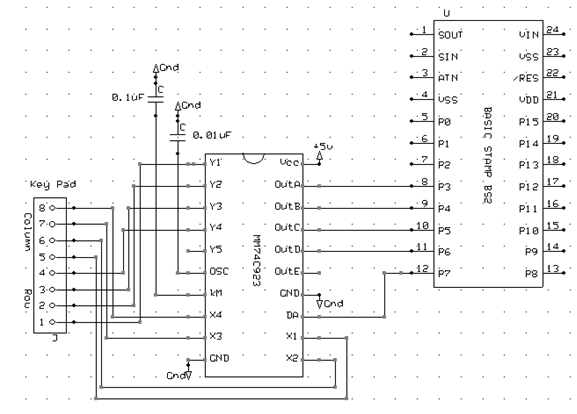
The encoder was connected to the keypad based on the information that given from the data sheet. The output was connected to 4 LED pins in the red board
Second way:-
We use 2 capacitor in Key bounce mask and oscillator to control the bouncing feature which happen when a key is pressed the contact bounce back and forth and settle down only after a small time delay (about 20ms). Even though a key is actuated once, it will appear to have been actuated several times. After connecting the circuit as shown in this schematic (the test was done without Microcontroller I just connect it to 4 LED and 1 pin for data available ).The output was blocked. In other word when the key pressed there is no output change in the LED all LED was OFF.

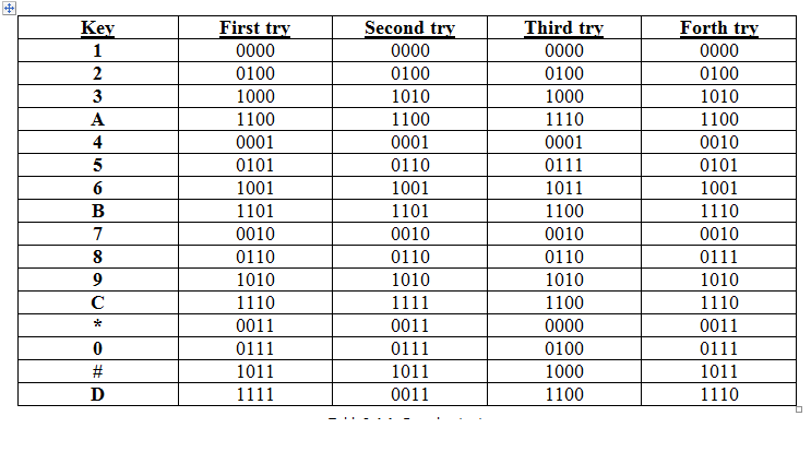
The result was collected based on four tries for each key. The result shows that the code doesn't equal the same key in the data sheet so there is an error.. The second way shows that the value of the key is blocked.

Im looking for solution for this problem and for code for the BS2
thanks so much
WbinHashel
Im senier student, im working in my project with basic stamp BS2. I was looking for code for my encoder but i didn't find. However, when Idid some test to my connection
First way:-
The encoder was connected to the keypad based on the information that given from the data sheet. The output was connected to 4 LED pins in the red board
Second way:-
We use 2 capacitor in Key bounce mask and oscillator to control the bouncing feature which happen when a key is pressed the contact bounce back and forth and settle down only after a small time delay (about 20ms). Even though a key is actuated once, it will appear to have been actuated several times. After connecting the circuit as shown in this schematic (the test was done without Microcontroller I just connect it to 4 LED and 1 pin for data available ).The output was blocked. In other word when the key pressed there is no output change in the LED all LED was OFF.
The result was collected based on four tries for each key. The result shows that the code doesn't equal the same key in the data sheet so there is an error.. The second way shows that the value of the key is blocked.
Im looking for solution for this problem and for code for the BS2
thanks so much
WbinHashel
577 x 414 - 44K
743 x 414 - 14K
Comments
so can I use 4 resisters ( 1K resister) to pull the input low ?
other thing .. there is a code that done for encoder? I need to test it by program.
thanks for replay
its give me different code now but it different than the data sheet code. I don't know why? I will try to re program the code in this case.
lets see what will happen
its work with this capacitors but it different than the data sheet code I don't know why ?
I will try to figure out the problem it need to be solved
My keypad and output is:
In order for your BS2 to use these outputs you will have to make a lookup table to convert the key position codes to whatever symbol is printed on the keytop. Such as.....
where Index is the value output by the 74C923 and Result will be whatever that key position represents.
can you please attach the code. I will test it in my circuit ..
thanks
http://www.rambal.com/descargas/libros/Nuts and Volts/4/Keypad Entry Display.pdf
I used Parallax 4 x 20 Serial LCD (Backlit) from Parallax Product ID 27979 : http://www.parallax.com/product/27979
its different than the connection in Nuts & Volts Column #97 May 2003. it used just 1 pin connected to MC. However I have 4 pin connected to MC to indicate the new data and 1 pin connected to show the data available.
I have problem with the code I don't have any Idea how I will make it. this is my first time I use this Microcontroller.
please help me