

PC power supply, into smart bench top power supply

Hello all,
This is my first post showcasing one of my projects.
I was in need of a power supply that had 3.3V, 5V, and 12V outputs. So I made a small 2A model. It worked (and still works), until I started trying to make a 3D printer. Once I got to the motors, I ran out of current. So I decided to use a computer power supply, but I was afraid I would blow something with the insane amount of current at my disposal.
I asked myself, How do I fix that? USE A PROP!! I thought the prop could monitor the current of all the outputs, and shut down the power supply if it sees a large increase of current. Then I thought, why stop at just monitoring. Why not display the voltage, & the current?
I starting figuring things out, and I decided not to show the current voltage, but to show the voltage percentage (-5% to +5%) of each voltage. Then I wanted to be able to see how much current was being required. So after many people helping me out on here, I came across microchip's PAC1710.
To display the info, I wanted it to be simple, show everything at the same time, adjust the full scale current(get to that later), and to be able to be seen from across the room. I could've used a monochrome 240x128 display, but It was not easy to see from across the room. So I tried LED's, that was the ticket. I started making a MAX7219 object, but I kept hitting walls(i'm not that great of a programer). So JonnyMac stepped in to save me. He created a MAX7219 object that worked great. I got the display part working, so I had boards made up for it. Now I have 3 display boards, 1 for 3.3V, 1 for 5V, and 1 for 12V. To show what voltage the boards are measuring, I got different color banana jacks (orange = 3.3V, red = 5V, yellow = 12V). After the all the parts for the display arrived, and I had the board populated, I tested it. It worked great.
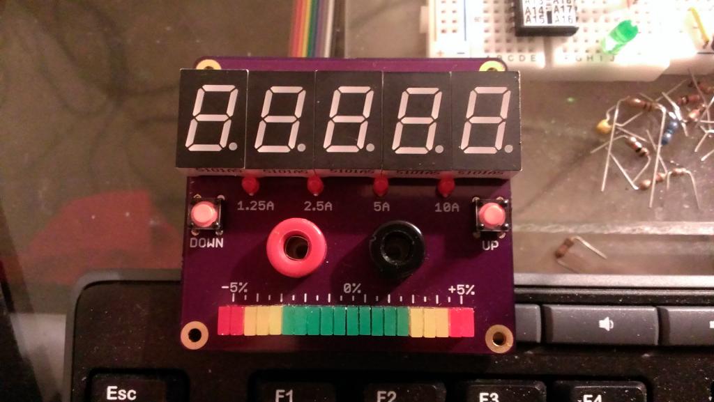
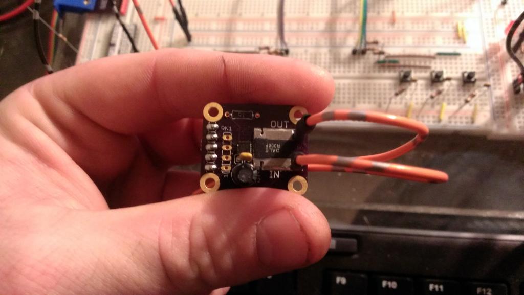
Then I started on the voltage, and current measurement. I decided on the PAC1710 to monitor the voltage and the current. The chip allows up to 40V input, and has 4 current references, 10mV, 20mV, 40mV, & 80mV. I figured I could use that to my advantage. Using a .008Ω resistor, I could have full scale current ranges of 1.25A, 2.5A, 5A, & 10A. That is why there are "up" and "down" buttons on the display board.
But the PAC1710 only comes in a 3mm x 3mm package(10-pin DFN). There was no way for me to be able to prototype with it, so I had to build a board first so I could work with it. But I screwed up on one of them. I am using a heat gun to solder the SMD parts on, and I got the board to hot. Some of the traces lifted off. So I am at a stopping point for now. It takes 2-4 weeks to get the PAC1710, since no one has them in stock.
Since I don't want to screw up again, and I know I will have more SMD projects. I have decided to put my effort on a reflow oven. Once that is done, I will come back to the power supply.
This is my first post showcasing one of my projects.
I was in need of a power supply that had 3.3V, 5V, and 12V outputs. So I made a small 2A model. It worked (and still works), until I started trying to make a 3D printer. Once I got to the motors, I ran out of current. So I decided to use a computer power supply, but I was afraid I would blow something with the insane amount of current at my disposal.
I asked myself, How do I fix that? USE A PROP!! I thought the prop could monitor the current of all the outputs, and shut down the power supply if it sees a large increase of current. Then I thought, why stop at just monitoring. Why not display the voltage, & the current?
I starting figuring things out, and I decided not to show the current voltage, but to show the voltage percentage (-5% to +5%) of each voltage. Then I wanted to be able to see how much current was being required. So after many people helping me out on here, I came across microchip's PAC1710.
To display the info, I wanted it to be simple, show everything at the same time, adjust the full scale current(get to that later), and to be able to be seen from across the room. I could've used a monochrome 240x128 display, but It was not easy to see from across the room. So I tried LED's, that was the ticket. I started making a MAX7219 object, but I kept hitting walls(i'm not that great of a programer). So JonnyMac stepped in to save me. He created a MAX7219 object that worked great. I got the display part working, so I had boards made up for it. Now I have 3 display boards, 1 for 3.3V, 1 for 5V, and 1 for 12V. To show what voltage the boards are measuring, I got different color banana jacks (orange = 3.3V, red = 5V, yellow = 12V). After the all the parts for the display arrived, and I had the board populated, I tested it. It worked great.
Then I started on the voltage, and current measurement. I decided on the PAC1710 to monitor the voltage and the current. The chip allows up to 40V input, and has 4 current references, 10mV, 20mV, 40mV, & 80mV. I figured I could use that to my advantage. Using a .008Ω resistor, I could have full scale current ranges of 1.25A, 2.5A, 5A, & 10A. That is why there are "up" and "down" buttons on the display board.
But the PAC1710 only comes in a 3mm x 3mm package(10-pin DFN). There was no way for me to be able to prototype with it, so I had to build a board first so I could work with it. But I screwed up on one of them. I am using a heat gun to solder the SMD parts on, and I got the board to hot. Some of the traces lifted off. So I am at a stopping point for now. It takes 2-4 weeks to get the PAC1710, since no one has them in stock.
Since I don't want to screw up again, and I know I will have more SMD projects. I have decided to put my effort on a reflow oven. Once that is done, I will come back to the power supply.

1024 x 577 - 66K

1024 x 577 - 58K
Comments
Good luck with the oven.
Thank You.