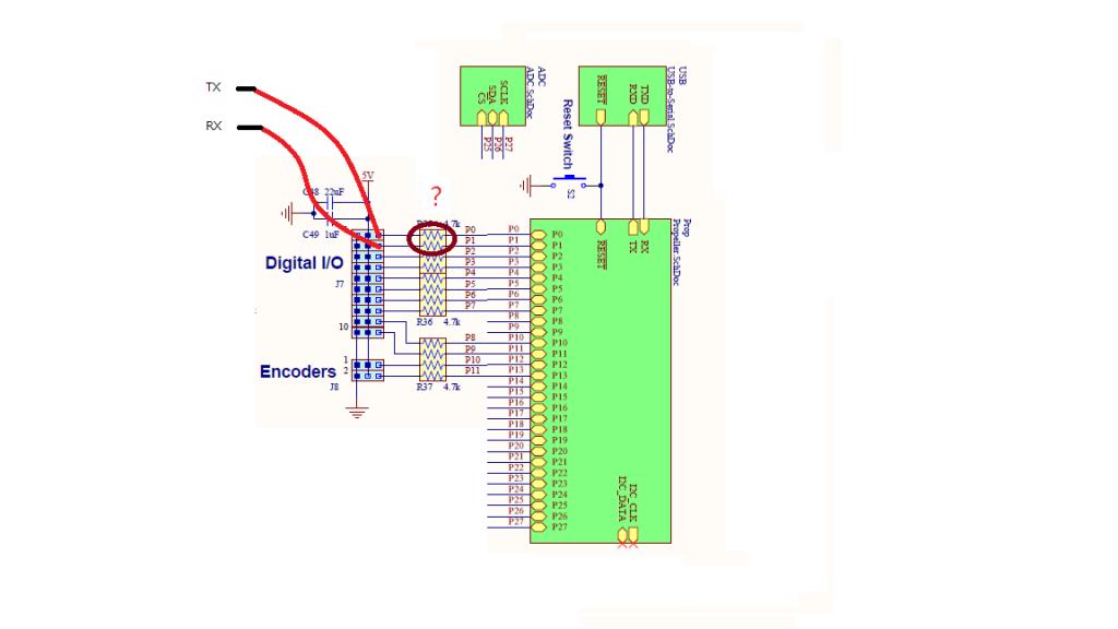
Using digital I/O Eddie Control Board for UART
I want to use FullDuplexSerial.spin as driver for UART in Eddie Control Board

My question 1 : Was the data transmission influenced by these resistors ?
My question 2 : Can the FullDuplexSerial.spin be used ?
Which experts can help me?

My question 1 : Was the data transmission influenced by these resistors ?
My question 2 : Can the FullDuplexSerial.spin be used ?
Which experts can help me?


Comments
2. Yes
The resistors provide protection to the Propeller I/O pins. You're safe to, at the very least, try out the communication with your external device. The main issue that you may encounter is transmitting to 5.0v devices, since the high of a Propeller I/O is only 3.3v and may not be enough to register on the external device.
These pins have null resistors on them ,but be careful to the voltage applied to them.
Brian
I am a novice.
I would not use these drivers, so I need some example to learn.
Someone can teach me or giving me some examples ?
What device do you want to integrate?
There's quite a few examples of using FDS out there.
what is FDS ? Can you give me website ?
thx~
FDS is FullDuplexSerial, which you linked to in your first post.
But the NRF24L01 does not have a UART interface, so FDS won't work for it. I see that you already have a thread on the subject: you should continue this conversation there. Duane has given a good reply.
http://forums.parallax.com/showthread.php/152424-Can-i-combine-nrf24l01-with-eddie-control-board
lt has UART interface.
Well, that's not exactly the NRF24L01 module that you want to interface to. You want to interface to a microcontroller with some unspecified protocol. I suspect that it's the standard wireless wire replacement scheme (whatever you transmit to RX appears on TX on everything else), but without a datasheet can't say for sure.
To try out what I would do is use two modules. One is connected directly to the Propeller with both RX and TX hooked up. The other one is powered and with a jumper on it's RX and TX. This will force it to loop everything that you send it back to the sender. So, from your Propeller you can simply transmit and see if you get those same bytes in your receive buffer.
That's an interersting board. I couldn't find any information about what firmware the board comes with if any. If you don't know how to program the STC15L204, you'll want to make sure it comes with program already loaded to interface with the nRF24L01+ modules.
I'm been meaning to make a similar board using an ATtiny. Apparently some of the ATtiny chips have an UART which would make the task of converting the SPI to serial easier. My thought was to include 2mm pitched holes so the board could be used as a XBee replacement.
If you purchase the STC15L204 board, I hope you report back here on your experience. I'm interested to know how well it works.
It looks like the board you're interested in uses 3.3V logic. The 4.7K resistors shouldn't be a problem with a 3.3V device. As SRLM mentioned, the resistors can cause problems with output to 5V devices.
I want to check your meaning. like this
Using Brian_B suggestion to set transmitter and then digital I/O as receiver.
TO Duane
My partner want to use STC15L204 board, but I have never used.
If it is possible,l will report my experience.