

Propeller RGB VU Meter

- Propeller Microcontroller
- MCP3002 ADC
- WS8211 72/m RGB LED strip
- Logic level shifter
- 4 resistors
- 2 capacitors
[video=youtube_share;dqCtIZwMXPw]
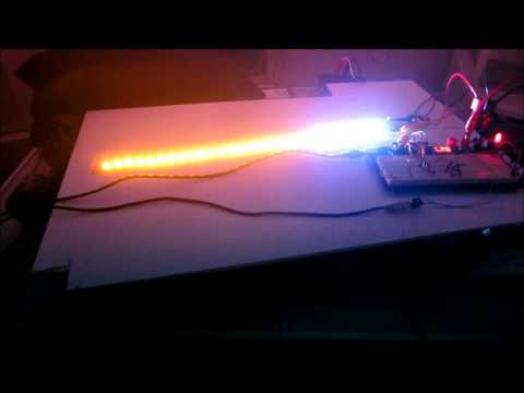
The camera doesn't work so well with all the flashing lights, but my next routines help a lot.
Big thanks to JonnyMac and whoever wrote the demo code for the ADC. It's great to be able to control a lot of LEDs without having to do a lot of soldering, the WS8211 strips are great for that and the Propeller handles them with ease.
The code below is a different effect than the video, and needs some work.
CON  '' MCP3208 - ADC code snippet demo **********************************
'>>>  READ THE MCP3208 DATA SHEET CAREFULLY for correct SPI timing pulses
'' Declare Objects & Variables
  _clkmode      = xtal1 + pll16x    'PLL Multiplier
  _xinfreq      = 5_000_000         'XTAL Frequency
''On Propeller Board                 On MCP3208 ic
''Symbol    Pin I/O   Function       Symbol Pin I/O  Function
  sdi           = 4  'Data  in   <-- SDO  2  Out Serial Data Output/SPI default
  sdo           = 5  'Data  out  --> SDI  4  In  Serial Data Input /SPI default
  clk           = 6  'Clock out  --> CLK  5  In  SerialClock Input /SPI default
''cs0 xxx       = 7  'CS    out  --> CS0  X  In  Chip Select Input /other ic (not used here)
  cs1           = 8  'CS    out  --> CS1  10 In  Chip Select Input /Analog-Digital Converter


  CLK_FREQ = ((_clkmode - xtal1) >> 6) * _xinfreq               ' system freq as a constant
  MS_001   = CLK_FREQ / 1_000                                   ' ticks in 1ms
  US_001   = CLK_FREQ / 1_000_000                               ' ticks in 1us


  RX1  = 31                                                     ' programming / terminal
  TX1  = 30

  SDA  = 29                                                     ' eeprom / i2c
  SCL  = 28


  LEDS = 1                                                     ' LED tx pin


OBJ
  DEBUG  : "FullDuplexSerial"       'add this in the same directory
    lcd  :  "SparkFun_serial_lcd"
    strip: "jm_ws2812"                                           ' WS2812 LED driver


VAR
  LONG ii, jj, command, channel, ADCvalue

  byte left
  byte right


  word addr
  byte ledp
  byte ledpb


dat


  Chakras               long    strip#RED, strip#ORANGE, strip#YELLOW
                        long    strip#GREEN, strip#BLUE, strip#INDIGO


PUB Main | posa,color1,color2,color3


  strip.start(LEDS, 32)
  waitcnt(clkfreq/100 + cnt)
  addr := strip.address

  dira[sdi]    := 0  'setSDI pin    = input
  outa[sdo]    := 0  'setSDO output = low
  dira[sdo]    := 1  'setSDO pin    = output
  outa[clk]    := 0  'setCLK output = low
  dira[clk]    := 1  'setCLK pin    = output
  outa[cs1]    := 1  'setCS  output = high = deselect chip
  dira[cs1]    := 1  'setCS  pin    = output ADC chip CS


  waitcnt(clkfreq + cnt)


 repeat


   left := adc3208(1)


   strip.fill(0, left/6, strip#blue)


   strip.set(left/6, $FF_00_00)


   pause(1)

   strip.fill(left/6, 32, 0_0_0)


PUB ADC3208(chan)           'get ADC voltage value
  channel      := chan      'save "channel"variable
  outa[cs1]    := 1         'Set CS1 output= high - preset value
  outa[clk]    := 1         'Set CLK output= high - preset clock pulse bf CS2
  outa[cs1]    := 0         'CS1 output low - start ADC
  outa[clk]    := 0         '>>>  READ THE MCP3208 DATA SHEET CAREFULLY <<<-----------------------
  command      :=(000 + chan) << (32-5)  'command Start, Single, Chan(xx)
  repeat 5                  'send 5 command bits - per Specification
     outa[sdo] := (command <-= 1) & 1
     outa[clk] := 1         'clock the command bit
     outa[clk] := 0
  outa[clk]    := 1         'set CLK output= high - one clock pulse after Command = 5th Clock pulse
  outa[clk]    := 0         'set CLK output= low  - set sample and hold ADC value
  outa[clk]    := 1         'set CLK output= high - one clock pulse after Command = 6th Clock pulse
  outa[clk]    := 0         'set CLK output= low  - end conversion = Null bit
  ADCvalue     := 0         'clear work variable =0
  repeat 10                 'read conversion 12 data bits                '***10 bit
     ADCvalue  := (ADCvalue << 1) | ina[sdi] 'input ADC data bit
     outa[clk] := 1         'clock ADC data bit
     outa[clk] := 0
  outa[clk]    := 0         'just to be sure = 0
  outa[cs1]    := 1         'CS1 output high - end ADC
  outa[clk]    := 0
  return ADCvalue

' End of demo


pub color_chase(p_colors, len, ms) | base, idx, ch


'' Performs color chase


  repeat base from 0 to len-1                                   ' do all colors in table
    idx := base                                                 ' start at base
    repeat ch from 0 to strip.num_pixels-1                      ' loop through connected leds
      strip.set(ch, long[p_colors][idx])                        ' update channel color
      if (++idx == len)                                         ' past end of list?
        idx := 0                                                ' yes, reset

    pause(ms)                                                   ' set movement speed


con


  ' Routines ported from C code by Phil Burgess (www.paintyourdragon.com)


pub color_wipe(rgb, ms) | ch


'' Sequentially fills strip with color rgb
'' -- ms is delay between pixels, in milliseconds


  repeat ch from 0 to strip.num_pixels-1
    strip.set(ch, rgb)
    pause(ms)


pub rainbow(ms) | pos, ch


  repeat pos from 0 to 255
    repeat ch from 0 to strip.num_pixels-1
      strip.set(ch, wheel((pos + ch) & $FF))
    pause(ms)


pub rainbow_cycle(ms) | pos, ch


  repeat pos from 0 to (255 * 5)
    repeat ch from 0 to strip.num_pixels-1
      strip.set(ch, wheel(((ch * 256 / strip.num_pixels) + pos) & $FF))
    pause(ms)


pub wheel(pos)


'' Creates color from 0 to 255 position input
'' -- colors transition r->g->b back to r


  if (pos < 85)
    return strip.color(255-pos*3, pos*3, 0)
  elseif (pos < 170)
    pos -= 85
    return strip.color(0, 255-pos*3, pos*3)
  else
    pos -= 170
    return strip.color(pos*3, 0, 255-pos*3)


pub wheelx(pos, level)                                          ' update by JonnyMac


'' Creates color from 0 to 255 position input
'' -- colors transition r-g-b back to r
'' -- level is brightness, 0 to 255


  if (pos < 85)
    return strip.colorx(255-pos*3, pos*3, 0, level)
  elseif (pos < 170)
    pos -= 85
    return strip.colorx(0, 255-pos*3, pos*3, level)
  else
    pos -= 170
    return strip.colorx(pos*3, 0, 255-pos*3, level)


con


  { ------------- }
  {  B A S I C S  }
  { ------------- }


pub pause(ms) | t


'' Delay program in milliseconds


  if (ms < 1)                                                   ' delay must be > 0
    return
  else
    t := cnt - 1776                                             ' sync with system counter
    repeat ms                                                   ' run delay
      waitcnt(t += MS_001)


pub high(pin)


'' Makes pin output and high


  outa[pin] := 1
  dira[pin] := 1


pub low(pin)


'' Makes pin output and low


  outa[pin] := 0
  dira[pin] := 1


pub toggle(pin)


'' Toggles pin state


  !outa[pin]
  dira[pin] := 1


pub input(pin)


'' Makes pin input and returns current state


  dira[pin] := 0


  return ina[pin]


dat


{{


  Terms of Use: MIT License


  Permission is hereby granted, free of charge, to any person obtaining a copy of this
  software and associated documentation files (the "Software"), to deal in the Software
  without restriction, including without limitation the rights to use, copy, modify,
  merge, publish, distribute, sublicense, and/or sell copies of the Software, and to
  permit persons to whom the Software is furnished to do so, subject to the following
  conditions:


  The above copyright notice and this permission notice shall be included in all copies
  or substantial portions of the Software.


  THE SOFTWARE IS PROVIDED "AS IS", WITHOUT WARRANTY OF ANY KIND, EXPRESS OR IMPLIED,
  INCLUDING BUT NOT LIMITED TO THE WARRANTIES OF MERCHANTABILITY, FITNESS FOR A
  PARTICULAR PURPOSE AND NON-INFRINGEMENT. IN NO EVENT SHALL THE AUTHORS OR COPYRIGHT
  HOLDERS BE LIABLE FOR ANY CLAIM, DAMAGES OR OTHER LIABILITY, WHETHER IN AN ACTION OF
  CONTRACT, TORT OR OTHERWISE, ARISING FROM, OUT OF OR IN CONNECTION WITH THE SOFTWARE
  OR THE USE OR OTHER DEALINGS IN THE SOFTWARE.


}}
The ADC is connected like this:
''* Example wiring would be as follows:                                             *
''*               R1                                                                *
''*     ADC─┳──┳──input                                                         *
''*       C1 R2                                                                 *
''*                                                                               *
''* R1: 10K (high impedance input is helpful, 10K should be the minimum)            *
''* R2: 100K (this effectively creates a voltage divider, but also drives input to  *
''*     zero volts when not in use)                                                 *
''* C1: 0.01µF (10000pF is the about the maximum you would want to use. The         *
''* capacitor reduces jitter or spikes but also reduces resolution).
Comments
I was able to implement a logarithmic response by using horrible coding instead of proper math. I used a bunch of IF statements. For example-
IF left =< 9
'turn first LED on
IF left => 10 AND left < 20
'turn second LED on
IF left => 20 AND left < 30
'turn third LED on
Effectively the power has to double to light up the next LED. I'm assuming that is how standard log taper works but working on that aspect as well.
If anyone has any comments on how to do that better I'm all ears.
[video=youtube_share;i0-VT5XDB2E]
[video=youtube_share;fJ3FbF0lbqA]
^^Please watch this at 1080 or it will seem out of foocus.
Still working out some kinks. Still waiting for parts for Xanadu Industrial Aēchos Rover 1! In the meantime all other aspects of life have been calling.
I'm going to black out the LED strips next.
It looks a lot better without the white strips. Some hot glue a frame, and notes in my code and this puppy is done!
This thing is awesome! I'm so glad I stumbled into it, as I am starting to venture into the realm of sound processing, and adding LEDs sounds like a logical next step. Do you have any plans to try out something with frequency analysis on those strips?
WMD
LEDs sell, that is for sure. Things that look good don't need a proper function these days, or maybe since the beginning of the human race. I think the LM3915 and that 10 segment LED bar is the first one I built, around 30 years ago. Since then I've always been a little obsessed with interactive music. Music is the best sensor source to drive just about anything entertaining.
For stereo you need two channels of ADC for each range of frequency you want. I ordered some MCP3008 awhile back to start playing with spectrum/EQ style display. Eight channel ADC divided by two channel audio give four different sets of inputs you can drive from the same two channel source. I am pretty sure all of this needs to be done on the analog input side of the ADC. I don't think there is any other way, at least using what I have to accomplish it.
On the input side of my two channel ADC I have toyed around with using RC filters to isolate low, medium and high freqs, it seems to work well. When I start to add all of this to an already busy WS8211 strip it starts to go south. I know a lot of that problem lies within my code, and what I'm working on now is this:
Low pass = red; band pass = blue; high pass = white. There is a lot of tinkering... er.. calibration in getting them equal, for instance the low pass doesn't give me close to the ADC value as the high pass.
I think I will post that version next. I just need to close out a few hundred trouble tickets first
I cut my project down to monaural for now, as a proof of concept. The red channel represents a 6 dB/o roll off above 160Hz and the green represents a 6dB/o roll down to 482Hz. The values are as close as I have parts as of now. You’d think all those capacitor and resistor assortment packs would get you somewhere with audio, but they don’t, I have drawers of components and unless I’m missing something I still don’t have what I would need.
I’ve included a very long and drawn out sweep from 20Hz to 20,000Hz as well, feel free to skip around to see the LEDs transition.
Easy RC Filter Calc = http://www.muzique.com/schem/filter.htm
[video=youtube_share;beJn1NAre8M]
Remember, audio is about proper reproduction, without the right equipment you're missing out.
[video=youtube_share;YwHSANdFwU8]
You need some good speakers, or headphone to hit the full sweep.
The screaming kid in the background is not mine, if it isn't the dogs bumping the desk with the infinity mirror you can be sure some other random effect to include laser printer calibration will impose.