Shop OBEX P1 Docs P2 Docs Learn Events
LED test circuit NOT bright..where did I go wrong ? — Parallax Forums

LED test circuit NOT bright..where did I go wrong ?

kt2050kt2050 Posts: 10
edited 2014-02-03 10:55 in General Discussion
Hi,

This is a test circuit I have followed to make two lights flash at different rates.
They will be used in a Star Trek model.

Attachment not found.
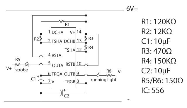
lighting-strobe-schematic.jpg


The test works and they flash....BUT hopelessly dim..
If anyone can tell me where I have gone wrong I would appreciate it.
Also I would like to add I`m really enjoying learning about electronics , however not
finding my brain power up to speed in this area..any help would be great.

I should add I`m using a 9v battery...and my capacitors are 10uf as specified but 10uf 100v

Thankyou, regards Kevin T.
638 x 368 - 26K

Comments

  • fengfeng Posts: 39
    edited 2014-02-02 02:08
    http://www.ti.com/lit/ds/symlink/lm555.pdf Page 9


    Charge time 0.693(R1 + R2)*C -> 0.91s
    Discharge time 0.693(R2)*C -> 0.08s


    Charge time 0.693(R3 + R4)*C -> 1.04s
    Discharge time 0.693(R4)*C -> 1.04s
  • kt2050kt2050 Posts: 10
    edited 2014-02-02 02:40
    feng wrote: »
    http://www.ti.com/lit/ds/symlink/lm555.pdf Page 9


    Charge time 0.693(R1 + R2)*C -> 0.91s
    Discharge time 0.693(R2)*C -> 0.08s


    Charge time 0.693(R3 + R4)*C -> 1.04s
    Discharge time 0.693(R4)*C -> 1.04s

    Thanks for your reply..sadly as a novice I dont understand what I need to do to make the LED brighter...whilst maintaining the flashing sequence I have for the project
  • Dr_AculaDr_Acula Posts: 5,484
    edited 2014-02-02 03:44
    Looks a pretty standard circuit. Hmm - start with the simple tests. Led and 150 ohm resistor across the battery. Is it bright or dim? (thinking first up, is the battery flat? Or - is the battery fine but somewhere in the layout is a short which is really lowering the battery volts). Do you have a voltmeter and if so, can you measure the volts on the battery when the circuit is running?
  • kt2050kt2050 Posts: 10
    edited 2014-02-02 03:51
    Hi...thanks for that...I've just got a volt meter...I will try all you have said.
  • PJAllenPJAllen Banned Posts: 5,065
    edited 2014-02-02 08:38
    Why is this in the Basic Stamp forum?
  • PublisonPublison Posts: 12,366
    edited 2014-02-02 08:52
    PJ Allen wrote: »
    Why is this in the Basic Stamp forum?

    Good question PJ.

    Moved to General Discussion.
  • Phil Pilgrim (PhiPi)Phil Pilgrim (PhiPi) Posts: 23,514
    edited 2014-02-02 09:14
    A couple things come to mind:

    1. Whose '556 are you using? Not all are created equal, and some have more output drive than others, particularly on the high side.

    2. It's possible that you've selected LEDs that just aren't bright. What happens when you connect one to 6V with the 150R resistor? Is it still dim?

    -Phil
  • kt2050kt2050 Posts: 10
    edited 2014-02-02 10:04
    My apologies for posting in the wrong place and
    thankyou for your replys.

    Following on from The Dr's advice I have tested the battery and tried another.
    However when I tried just a 150 or 120 resistor across the battery it was still just as dim,and
    when I tried a 1k resistor it was as bright as I would like .. so I guess I need a lower resistor.
    The maths of which though is just beyond me..
  • Phil Pilgrim (PhiPi)Phil Pilgrim (PhiPi) Posts: 23,514
    edited 2014-02-02 10:09
    kt2050 wrote:
    However when I tried just a 150 or 120 resistor across the battery ...
    Did you mean that, or did you put the resistor in series with the LED?

    -Phil
  • Peter JakackiPeter Jakacki Posts: 10,193
    edited 2014-02-02 10:32
    kt2050 wrote: »
    Hi,

    This is a test circuit I have followed to make two lights flash at different rates.
    They will be used in a Star Trek model.

    Attachment not found.
    lighting-strobe-schematic.jpg


    The test works and they flash....BUT hopelessly dim..
    If anyone can tell me where I have gone wrong I would appreciate it.
    Also I would like to add I`m really enjoying learning about electronics , however not
    finding my brain power up to speed in this area..any help would be great.

    I should add I`m using a 9v battery...and my capacitors are 10uf as specified but 10uf 100v

    Thankyou, regards Kevin T.

    When you say V+ and V- are you saying that there are other voltages besides the 6V? Could it be that you have cooked the LEDs because it sounds either that the 150R resistors are 15R or else they are 150K. Methinks a photo is in order.

    TIp: Never say V- when it is in fact the common reference rail from which the supply voltage is measured from. A V- infers that there is also a voltage that is more negative than your common and likewise V+.. Also write 6V+ simply as +6V as that is the nominal voltage. So the LEDs could easily have been drawn with a wire going to common and one to +6V, no more confusion.

    BTW, post#4 is very confusing as you say "when I tried a 1k resistor it was as bright as I would like" or did you mean wasn't as bright?
  • kt2050kt2050 Posts: 10
    edited 2014-02-02 10:55
    Did you mean that, or did you put the resistor in series with the LED?

    Hi Phil,

    I placed a resistor between the LED and battery and then lit it from there.
  • Phil Pilgrim (PhiPi)Phil Pilgrim (PhiPi) Posts: 23,514
    edited 2014-02-02 10:57
    Per Peter's inquiry, are you sure your 150R resistor isn't 150K? What is the color code?

    -Phil
  • kt2050kt2050 Posts: 10
    edited 2014-02-02 11:04
    This diagram is not my own .. and I'm not doing too well with it.
    My receipt for the resistors states..150k....now I see that R5 and R6 just says 150 and R3 470.
    I bought 150k and 470k.
    This must be where I've gone wrong..?
  • Phil Pilgrim (PhiPi)Phil Pilgrim (PhiPi) Posts: 23,514
    edited 2014-02-02 11:06
    kt2050 wrote:
    I bought 150k and 470k.
    This must be where I've gone wrong..?

    Yup.

    -Phil
  • kt2050kt2050 Posts: 10
    edited 2014-02-02 11:12
    Lol...an obvious mistake to you...but I doubt I would have found it...thanks to all for help given.
  • davejamesdavejames Posts: 4,047
    edited 2014-02-02 19:18
    kt2050 wrote: »
    Lol...an obvious mistake to you...but I doubt I would have found it...thanks to all for help given.

    kt2050 - is this issue solved? If so, it would be good to mark the original post as "solved" so other readers know.
  • LoopyBytelooseLoopyByteloose Posts: 12,537
    edited 2014-02-03 02:00
    Yes indeed, even here in the remote island of Taiwan, the retailers get their packaging mixed up and the resistors are not the labeled value. Or customers toss the 150K in the 150R bin when they change their mind.

    Hardly worth going back to the store for a refund or return on 10 resistors, but a nightmare if you don't check the value with a multimeter as you build.

    I have a nice big pile of 10 megaohm resistors that were sold to me as 10 K ohm. next to useless <sigh>

    At least with 150K and 470K, you might someday find something to use them for (an op amp project).
  • LeonLeon Posts: 7,620
    edited 2014-02-03 02:29
    I was once supplied with some resistors that were wrongly marked.
  • kt2050kt2050 Posts: 10
    edited 2014-02-03 06:22
    davejames wrote: »
    kt2050 - is this issue solved? If so, it would be good to mark the original post as "solved" so other readers know.

    A visit to Maplins this morning and with correct resistors fitted the LEDs are as bright as
    I wanted..something learned...many thanks to all.
  • xanatosxanatos Posts: 1,120
    edited 2014-02-03 09:28
    So what Star Trek model are these being used in?
  • kt2050kt2050 Posts: 10
    edited 2014-02-03 10:55
    xanatos wrote: »
    So what Star Trek model are these being used in?

    Hi...its the Polar Lights Enterprise refit...but the small 1/1000 ...my plan is to use a mix of LEDs and fibre optics.
    Progress is steady...but for me...functioning within normal parameters..
Sign In or Register to comment.